
Airflow powder grinding system and powder treatment process

A treatment process and airflow technology, which is applied in the field of jet mill pulverization system and powder treatment process, can solve the problems of sticky particles clogging the nozzle, high powder crushing cost, and imprecise particle powder, so as to reduce the crushing cost and improve the screening efficiency And cleaning efficiency, improve the effect of crushing precision

Inactive Publication Date: 2015-11-25
四川省有色冶金研究院有限公司
View PDF5 Cites 6 Cited by
  • Summary
  • Abstract
  • Description
  • Claims
  • Application Information

AI Technical Summary

Problems solved by technology

[0003] The technical problem to be solved by the present invention is to improve the technical problem of sticky particles clogging the nozzle, and further solve the problem of high gas drying cost. Problems of high cost and imprecise particle powder

Method used


Image

  • Airflow powder grinding system and powder treatment process
  • Airflow powder grinding system and powder treatment process

Examples


Embodiment 1

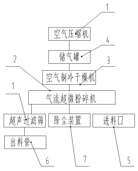
[0021] like figure 1 As shown, a jet mill powder system includes an air compressor 1 and a jet pulverizer 2 connected in sequence, an air refrigerator 3 is connected between the air compressor 1 and the jet pulverizer 2, and the air refrigerator The air inlet of 3 is connected to the air compressor 1, and the air outlet of the air refrigerator 3 is connected to the airflow ultrafine pulverizer 3; an air storage tank 4 is connected between the air compressor 1 and the air refrigerator 3, and the airflow ultrafine The pulverizer 3 is connected with a dust removal device 7;

[0022] The dust removal device 7 includes a gas outlet, which is used to purify the separated medium gas, and discharge the medium gas through the gas outlet to the gas intake port for recycling and continue to carry the sticky powder particles for pulverization .

[0023] The airflow ultrafine pulverizer 2 includes a crushing area and a classification area. The pulverization area is located at the bottom ...

Embodiment 2

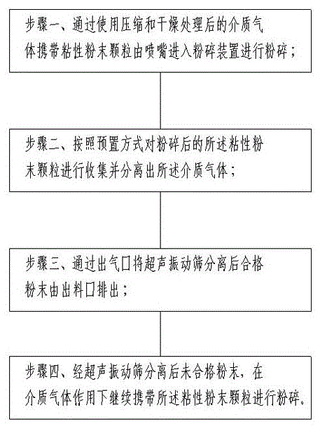
[0026] like figure 2 Shown, a kind of powder processing technology is characterized in that, comprises:

[0027] Step 1, using compressed and dried medium gas to carry cohesive powder particles from the nozzle into the crushing device for crushing;

[0028] Step 2, collecting the pulverized sticky powder particles according to a preset method and separating the medium gas;

[0029] Step 3. After the qualified powder is separated by the ultrasonic vibrating screen through the air outlet, the qualified powder is discharged from the outlet;

[0030] Step 4: After the unqualified powder is separated by the ultrasonic vibrating sieve, the viscous powder particles are continued to be crushed under the action of the medium gas.

[0031] Using the compressed and dried medium gas to carry sticky powder particles from the nozzle into the crushing device for crushing specifically includes: obtaining the medium gas in the space through the air intake port; compressing and drying the ob...


PUM


Abstract

The invention discloses an airflow powder grinding system and a powder treatment process. The airflow powder grinding system comprises an air compressor and an airflow ultrafine grinder which are sequentially connected. An air refrigerator is connected between the air compressor and the airflow ultrafine grinder. An air inlet of the air refrigerator is connected the air compressor, and an air outlet of the air refrigerator is connected with the airflow ultrafine grinder. An air storage tank is connected between the air compressor and the air refrigerator, and the airflow ultrafine grinder is connected with a dust removal device. By means of an airflow ultrafine grinding system, the temperature of compressed air can be lowered, and it is guaranteed that the components and effect of powder are not changed. An ultrasonic vibration screen is adopted, so that adhesion, friction, flat reducing, wedging in and other screen blocking factors can be restrained through ultrasonic vibration waves attached to the screen, screening efficiency and screen cleaning efficiency are improved, grinding precision is improved, and grinding cost is reduced.

Description

technical field [0001] The invention relates to an airflow milling device and a powder grinding method, in particular to an airflow milling system and a powder processing process. Background technique [0002] Jet mill is widely used in the production of non-metallic minerals and chemical raw materials. Its principle is to drive the high-speed airflow to move the materials at high speed, so that the materials collide with each other and grind them by friction. The current ultra-fine pulverization technology can be a variety of pulverization methods, such as mechanical impact pulverizers, vibrating mills, jet pulverizers, stirring mills, etc. Among them, the jet mill is under the action of high-speed airflow, the material is crushed through the impact between the powder particles, the impact and shearing effect of the airflow on the material, and the impact, friction and shearing of the material and other parts. However, the existing jet milling technology generally exists i...

Claims


Application Information

Patent Timeline
Patent Type & Authority Applications(China)
IPC IPC(8): B02C19/06
Inventor 万宁李海英邹善方刘晔朱冬
Owner 四川省有色冶金研究院有限公司
Learn More