A method for treating oil residue produced in the dairy sewage treatment process

A technology of sewage treatment and treatment method, which is applied in the field of waste oil residue and oil treatment, can solve the problems of high transportation cost, high comprehensive cost, and containing sludge, and achieve the effect of saving chemical costs and transportation costs

Active Publication Date: 2018-04-24
BEIJING JIANYAN ENVIRONMENTAL PROTECTION EQUIP
View PDF4 Cites 0 Cited by
  • Summary
  • Abstract
  • Description
  • Claims
  • Application Information

AI Technical Summary

Problems solved by technology

[0003] However, it is difficult to treat the oil residue contained in the wastewater discharged by dairy enterprises, especially the oil residue separated from the sewage.
On the one hand, the oil residue separated from the sewage, compared with the oil in the general kitchen industry, has a relatively complex composition and contains sludge, suspended solids, etc., which is not completely suitable for the production of biodiesel; on the other hand, due to The COD concentration of oil residue is usually very high, generally 28~30×10 4 mg / l, substances of this concentration cannot be absorbed by general sewage treatment systems
In the third aspect, dairy production plants are generally located in relatively remote parks, and there is no biodiesel production base nearby. Moreover, since the output of oil residue is relatively small, if long-distance transportation is used, the transportation cost is high, and the overall cost is higher than the income.
[0004] At present, the usual treatment method for this part of the oil residue produced in dairy enterprises is to compress it together with the sludge in the sewage plant, dehydrate it, and then transport it abroad. Generally, further sludge treatment, such as landfill, is required. Higher transportation costs and sludge disposal costs

Method used


Image

  • A method for treating oil residue produced in the dairy sewage treatment process

Examples


Embodiment Construction

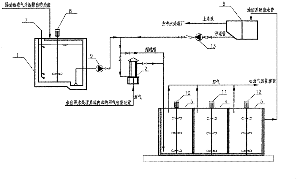
[0018] Below in conjunction with accompanying drawing, process flow of the present invention is described in detail

[0019] In the process of dairy waste water treatment, solid oil residue lighter than water will be produced in the grease trap or air flotation tank. The present invention treats this part of the oil residue and changes its state from a solidified state that is lighter than water to a solid state that can be mixed with water. In the liquid state of water miscibility, the COD of oil residue is greatly reduced to the acceptable range of the sewage treatment system, so that it can directly enter the sewage treatment system, and can be degraded and treated in the sewage plant. Proceed as follows:

[0020] (1) pretreatment, the oil residue separated from the grease trap or the air flotation tank is collected into the oil storage tank 1, and the mixer 8 is set in the oil storage tank 1, and mechanical stirring is performed to fully homogenize the oil residue; the oil...


PUM


Abstract

The invention discloses a method for treating oil residue produced in the process of sewage treatment of dairy products, which belongs to the field of processing waste animal oil residue produced in the process of sewage treatment, and includes several steps of pretreatment, liquefaction, fermentation, and precipitation. The pretreatment process removes the oil residue Mechanical stirring is sufficient and homogeneous. If the temperature is continuously lower than 10°C for more than 24 hours, the oil residue is heated to control the temperature; after pretreatment, the oil residue is liquefied by special bacteria, and the solid is converted into liquid and water-miscible sewage, reducing the COD: the oil residue liquefied into sewage enters the fermentation tank for fermentation and degradation, reduces COD pollutants, thereby reducing the load on the sewage treatment system, the supernatant after precipitation enters the sewage treatment system, and the precipitated sludge returns to the oil residue for heating or directly into the oil residue liquefier to supplement bacteria. The invention adopts in-situ biological treatment technology. After the oil residue is treated in the system, it directly enters the sewage treatment system for degradation and treatment, realizing the digestion of pollutants in the plant.

Description

technical field [0001] The invention relates to the field of animal oil residue treatment, in particular to a treatment method for waste oil residue generated in the process of dairy sewage treatment. Background technique [0002] The content related to oil residue treatment technology mainly focuses on kitchen waste oil residue. The treatment of this type of oil residue mainly includes simple heating, refining, recycling and biodiesel production. [0003] However, it is difficult to treat the oil residue contained in the wastewater discharged by dairy enterprises, especially the oil residue separated from the sewage. On the one hand, the oil residue separated from the sewage, compared with the oil in the general kitchen industry, has a relatively complex composition and contains sludge, suspended solids, etc., which is not completely suitable for the production of biodiesel; on the other hand, due to The COD concentration of oil residue is usually very high, generally 28~3...

Claims


Application Information

Patent Timeline
Patent Type & Authority Patents(China)
IPC IPC(8): B09B3/00B09B5/00
Inventor 牛庆中张红艳钮劲涛
Owner BEIJING JIANYAN ENVIRONMENTAL PROTECTION EQUIP
Why Eureka
Try Eureka