Beam clamping and fixing device

A fixing device, clamping and fixing technology, which is applied in the directions of auxiliary devices, transportation and packaging, vehicle parts, etc., can solve the problem of heavy columnar structure of the beam body fixing platform, easy left and right sliding of the beam structure, and the space of the beam body clamping platform Limited and other problems, to achieve the effect of simple and convenient connection, simple structure, and light structural design

Active Publication Date: 2015-11-25
ZHUZHOU ELECTRIC LOCOMOTIVE CO
View PDF12 Cites 2 Cited by
  • Summary
  • Abstract
  • Description
  • Claims
  • Application Information

AI Technical Summary

Problems solved by technology

This results in limited space on the beam clamping platform, and for beams with complex structures, the space is insufficient
[0007] 3. The long column structure of the beam fixed platform is too bulky
[0008] 4. The left and right degrees of freedom of the structure are insufficiently constrained. When the beam body bears a large horizontal force, the beam structure is prone to slide left and right
[0009] 5. The design structure of the left and right horizontal position adjustment of the beam pad on the beam clamping platform has the disadvantages of difficult operation and easy damage of bolts.
[0010] 6. Due to the limited space of the beam body clamping platform, the height of the beam pad 103 needs to be adjusted during the beam clamping process, which has the disadvantages of many components, difficult operation, easy damage, and low work efficiency.
[0011] To sum up, the project of the clamping and fixing device of the center beam in the prior art has low versatility, and cannot be applied to the production of different types of vehicles such as magnetic levitation and intercity EMUs

Method used


Image

  • Beam clamping and fixing device
  • Beam clamping and fixing device
  • Beam clamping and fixing device

Examples


Embodiment Construction

[0070] For the convenience of description, the description of the relative positional relationship of each component (such as: upper, lower, left, right, etc.) is described according to the layout direction of the drawings in the specification.

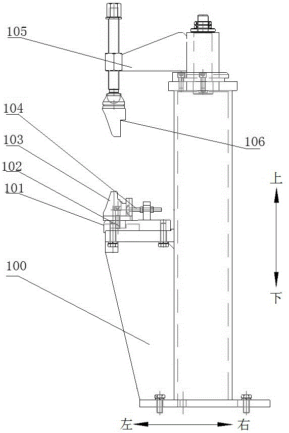
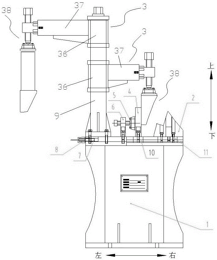
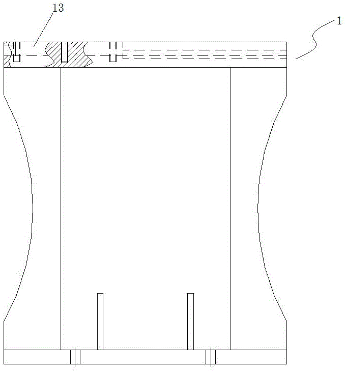
[0071] Such as Figure 2-18 As shown, a beam clamping and fixing device includes a base 1, a stand 9 fixed on one end of the upper surface of the base 1, two pressing arms 3 that are set at different heights on the stand 9 and can rotate relative to the stand 9, and Beam blocks 2 that can move horizontally on the base 1.

[0072] The pressing arm 3 includes a vertical arm 36 sleeved on the column 9, a telescopic horizontal arm 37 vertically fixed to the vertical arm 36, and a beam clamping head 38 vertically installed on the front end of the horizontal arm 37. The head 38 is parallel to the vertical arm 36 and movable in the vertical direction.

[0073] The horizontal arm 37 includes a cylinder sleeve 39 and a piston arm 40 sleeved ...


PUM


Abstract

The invention discloses a beam clamping and fixing device. The beam clamping and fixing device is characterized in that the beam clamping and fixing device comprises a base, a stand column fixed to one end of the upper surface of the base, at least one pressing arm arranged on the stand column in a sleeving manner and capable of rotating relative to the stand column, and a beam cushion block capable of horizontally moving on the base; and each pressing arm comprises a vertical arm arranged on the stand column in a sleeving manner, a telescopic horizontal arm perpendicularly fixed to the vertical arm, and a beam clamping head perpendicularly arranged at the front end of the horizontal arm, wherein the beam clamping head is parallel to the vertical arm and can move in the vertical direction. According to the beam clamping and fixing device, the brand-new structural design is adopted, and the problems that in the prior art, the operation space is small and the beam restraining force is not enough are solved. The beam clamping and fixing device has the beneficial effects of being simple in structure, low in production and maintenance cost, high in universality and firm and reliable in clamping.

Description

technical field [0001] The invention belongs to the field of basic tooling design, and in particular relates to a beam clamping and fixing device. It is especially suitable for assembly and welding of the top cover of urban rail vehicles. Background technique [0002] The beam body clamping device is widely used in the manufacturing industry. Currently, the roof assembly welding tool used is figure 1 As shown, the structure is mainly composed of a seat body 100, a connecting seat 101, a pull block 102, a beam cushion block 103, a T-slot bolt 104, a pressing arm 105, a beam pressing block 106, and an adjusting gasket. [0003] The main feature of this mechanism is that the left side of the seat body is the beam body clamping platform, and the right side is the beam body fixing platform. It is successfully placed on the clamping platform. In order to ensure the position adjustment of the beam cushion block, the left and right position movement is controlled by T-slot bolts 1...

Claims


Application Information

Patent Timeline
IPC IPC(8): B23K37/04
CPCB23K37/04B23K2101/006
Inventor 黄军才吴志明彭章祝侍光磊李本广刘益武
Owner ZHUZHOU ELECTRIC LOCOMOTIVE CO
Why Eureka
Try Eureka