Double-layer cross-shaped self-drilling anchor bolt drill bit

A bolter bit, self-drilling technology, applied in the direction of drill bit, drilling equipment, earthwork drilling and mining, etc., can solve the problems of increasing the resistance between the drill bit and the rock and soil on the hole wall, easy drilling deviation and swing, small slag discharge groove of the cross bit, etc. , to achieve the effect of reducing swing, reducing heat and improving life

Active Publication Date: 2015-11-25
洛阳中岩工程材料有限公司
View PDF6 Cites 3 Cited by
  • Summary
  • Abstract
  • Description
  • Claims
  • Application Information

AI Technical Summary

Problems solved by technology

The cutting edge of the cross drill bit is located on the top of the drill bit, and the cutting edge is distributed in a cross shape on a plane; since the cutting edge is on a plane, it is easy to cause deviation and swing during the drilling process, and the slag discharge groove of the cross drill bit is larger. The small size leads to poor slag discharge, which intensifies the resistance between the drill bit and the hole wall rock and soil during drilling; on the one hand, the above reasons will lead to easy hole collapse when drilling in loose soft soil layers; Premature wear, affecting drilling depth

Method used


Image

  • Double-layer cross-shaped self-drilling anchor bolt drill bit
  • Double-layer cross-shaped self-drilling anchor bolt drill bit
  • Double-layer cross-shaped self-drilling anchor bolt drill bit

Examples


Embodiment 1

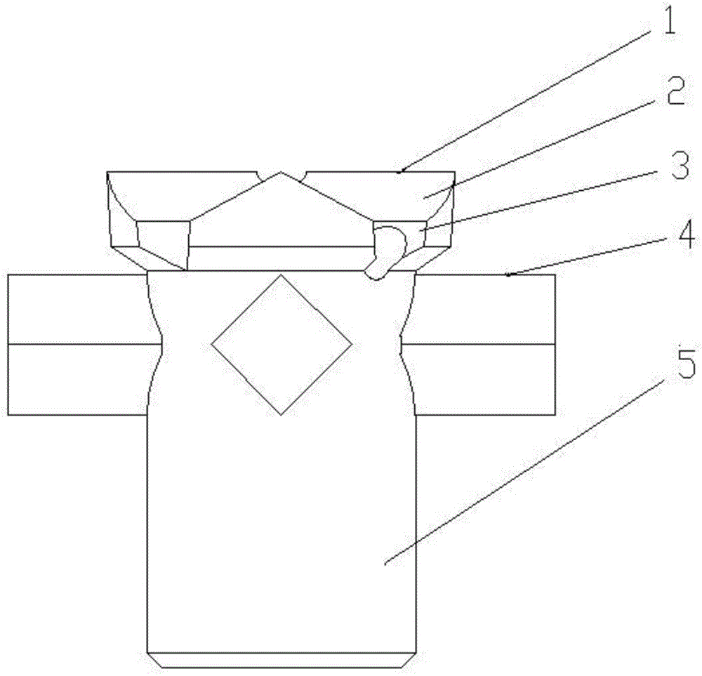
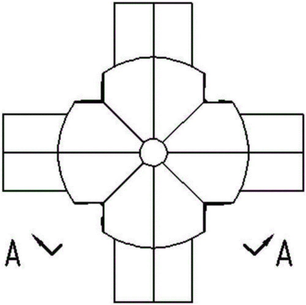
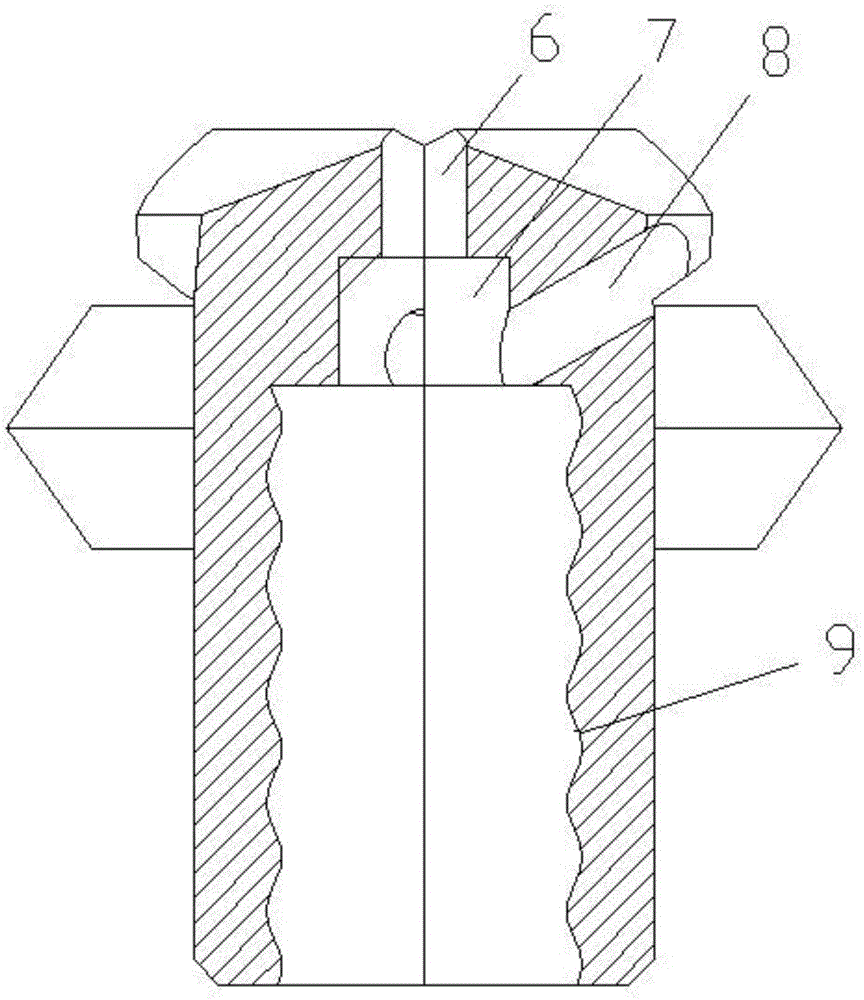
[0027] Such as figure 1 , figure 2 As shown, a double-headed cross self-drilling anchor drill bit of this patent includes a main cutting edge 1, 4 symmetrical upper slag discharge grooves 2, 4 symmetrical lower slag discharge grooves 3, 4 secondary cutting edges 4, 1 6 upper water holes, 2 side water holes 8, drill trouser body 5, internal thread 9, transition hole 7; the main cutting edge 1 is a cross edge connected to the blade, located at the top of the drill bit, and the main cutting edge 1 edge The blades are on the same plane, the diameter of the circumference of the blade is about 1.2 times the diameter of the pants body 5, and the circumference of the blade has a downward clearance angle of 1° to 2°, and the downward chamfer of 120-130° with the axis Connected with the drill body 5; the 4 secondary cutting edges 4 have the same shape, and are evenly distributed on the upper edge of the drill body 5 towards the top, and the 4 secondary cutting edges 4 are on the same ...


PUM


Abstract

The invention discloses a double-layer cross-shaped self-drilling anchor bolt drill bit. The double-layer cross-shaped self-drilling anchor bolt drill bit comprises a main cutting edge, four auxiliary cutting edges, four upper symmetrical residue discharging grooves, four lower symmetrical residue discharging grooves, one upper water hole, two lateral water holes, a drill bit trouser, an internal thread and a transition hole. The main cutting edge is a cross-shaped edge where edge parts are connected, the four auxiliary cutting edges are evenly distributed around the trouser in a cross shape, and the edge parts of the auxiliary cutting edges face the top of the drill bit. The upper residue discharging grooves and the cross-shaped edge are distributed in a spaced mode, the lower residue discharging grooves are connected with the upper residue discharging grooves, and the upper and lower residue discharging grooves are of V-type structures. The upper water hole is a through hole, and the axis of the upper water hole coincides with the axis of the drill bit. The lateral water holes are through holes, one end of each lateral water hole is through the transition hole, and the other end of each lateral water hole is located at the junction point of the corresponding upper residue discharging groove and the corresponding lower residue discharging groove. The internal thread is located at the tail of the drill bit, and the transition hole is located in the bottom of the internal thread. The guiding capacity and the residue discharging capacity of the drill bit can be enhanced, then hole collapse in soft soil layer drilling is improved, and the drilling depth is increased.

Description

technical field [0001] The invention relates to the field of drill bits, in particular to a double-layer cross self-drilling anchor drill bit. Background technique [0002] Because the self-drilling bolt has the functions of drilling, grouting and anchoring, compared with ordinary steel bolts, there is no need to return the drill pipe and insert the bolt, which can greatly shorten the construction period; in addition, with the rock With the development of soil anchoring technology, the geological conditions used for anchor rods are becoming more and more harsh. Ordinary steel anchor rods can no longer solve the problems faced during construction in some special address conditions, especially when drilling in broken and loose rock and soil. Facing the hole collapse problem. As the most effective method to improve the stability of geotechnical engineering, self-drilling bolts are widely used in domestic and foreign railways, highways, tunnel construction, underground infrastr...

Claims


Application Information

Patent Timeline
Patent Type & Authority Applications(China)
IPC IPC(8): E21B10/42
Inventor 许岩波孙晓刚杜景景肖盼盼张娟娟
Owner 洛阳中岩工程材料有限公司
Why Eureka
Try Eureka