Steam recycling method

A technology of steam and steam drum, which is applied in the direction of steam generation method using heat carrier, steam engine device, process efficiency improvement, etc. It can solve the problems of high temperature heating equipment damage, safety hazards, gas tempering, etc., and achieve the effect of saving electric energy

Inactive Publication Date: 2015-11-25
张更生
View PDF5 Cites 2 Cited by
  • Summary
  • Abstract
  • Description
  • Claims
  • Application Information

AI Technical Summary

Problems solved by technology

This poses a safety hazard during the operation of the heating equipment. Once the power supply stops due to a fault, the high-temperature heating equipment will be damaged, and in severe cases, it will explode due to gas backfire

Method used


Image

  • Steam recycling method

Examples


Embodiment Construction

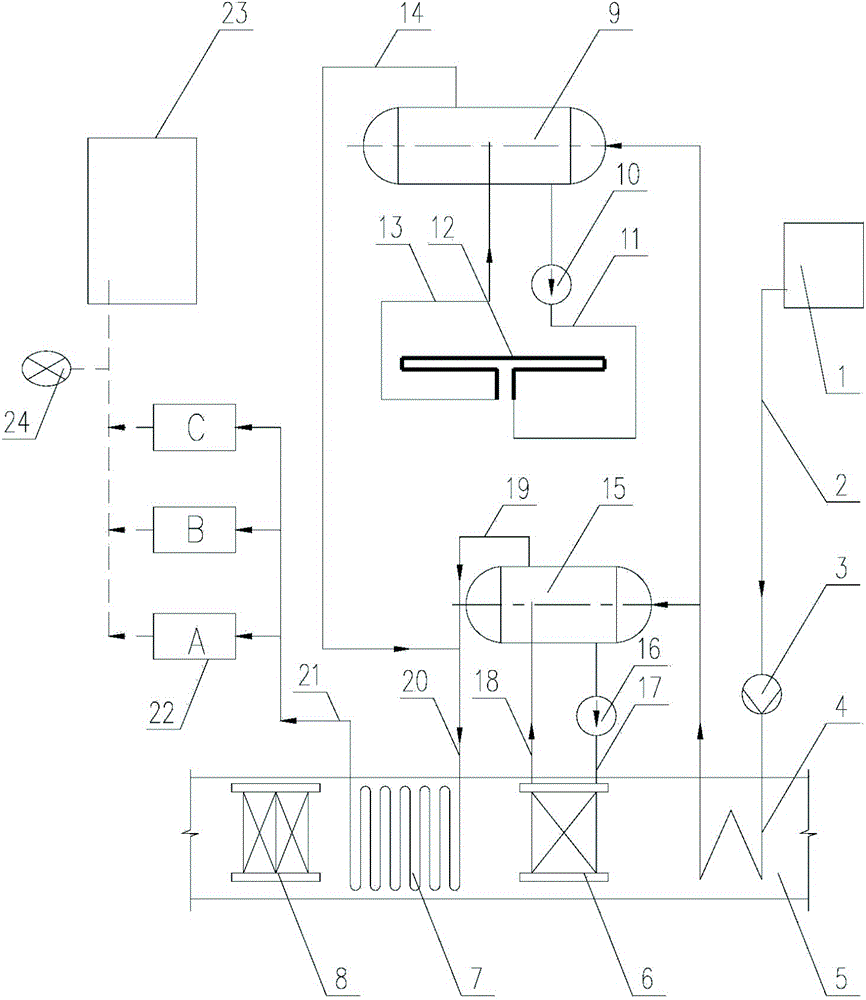
[0016] Such as figure 1 As shown, a method of steam recovery and utilization in the present invention includes a heat exchanger 8, a steam superheater 7, an evaporator 6 and an economizer 4 arranged in sequence in the heating flue gas pipeline 5, and the inlet of the economizer The water outlet is connected to the soft water tank 1 through the soft water supply pipe 2, and the water supply pump 2 is arranged on the soft water supply pipe;

[0017] The system also includes a first steam drum 9 and a second steam drum 15, wherein the first steam drum and the second steam drum communicate with the water outlet of the economizer through pipelines respectively, and the first steam drum The first steam drum communicates with the outlet and the inlet of the vaporization cooling unit 12 through the first pipe group, and the second steam drum communicates with the air inlet and the gas outlet of the evaporator through the second pipe group, and the first steam drum The second steam dr...


PUM


Abstract

The invention discloses a steam recycling method. The method includes an economizer, an evaporator, a steam overheating device and a heat exchanger which are sequentially arranged in a flue of a heating furnace. A softened water tank is connected with the economizer. The economizer is connected with steam pockets. The steam pockets are connected with a steam discharge main pipe through steam discharge branch pipes. The steam discharge main pipe is connected with the steam overheating device arranged in the flue of the heating furnace. The steam overheating device is connected with a hot steam discharge main pipe which is connected with an intelligent power generator set. The intelligent power generator set is connected with an electricity receiving cabinet of the heating furnace and a power network. By means of the steam recycling method, waste heat of smoke of the heating furnace can be utilized to the maximum extent, all steam produced by the heating furnace is used for meeting the production requirements of electricity-consuming devices of the heating furnace, and therefore all the devices of the heating furnace can achieve self-sufficiency of electricity, and safety and reliability are achieved.

Description

technical field [0001] The invention relates to the field of recovery and utilization of waste heat, in particular to a method for recovery and utilization of steam. Background technique [0002] In the field of industrial furnaces, after the flue gas in the industrial furnace passes through the heat exchanger installed in the flue, the exhaust gas temperature is generally about 400°C, and the waste heat in this part of the flue gas is usually not recovered, but directly discharged into the atmosphere , resulting in a great waste of energy; in the field of industrial furnaces, the power supply of heating equipment is usually supplied by the external network. For large joint enterprises, the power supply of heating equipment is usually set to two power sources, one for production power and the other for security power; for small private enterprises, the power supply of heating equipment is usually set to one for production power. Set security power. This poses a safety haza...

Claims


Application Information

Patent Timeline
Patent Type & Authority Applications(China)
IPC IPC(8): F27D17/00F22B1/18F01K11/00
CPCY02P10/25Y02P80/15
Inventor 张更生
Owner 张更生
Why Eureka
Try Eureka