
Semiconductor layer surface roughening method and formation method for LED structure with roughened surface

A surface roughening and semiconductor technology, which is applied in semiconductor devices, electrical components, circuits, etc., can solve the problems of uneven etching and poor stability, and achieve the effect of controllable roughness, good stability and good uniformity

Inactive Publication Date: 2015-11-25
HUIZHOU BYD IND
View PDF9 Cites 5 Cited by
  • Summary
  • Abstract
  • Description
  • Claims
  • Application Information

AI Technical Summary

Problems solved by technology

[0004] The present invention aims to overcome the shortcomings of uneven etching and poor stability in the prior art

Method used


Image

  • Semiconductor layer surface roughening method and formation method for LED structure with roughened surface
  • Semiconductor layer surface roughening method and formation method for LED structure with roughened surface
  • Semiconductor layer surface roughening method and formation method for LED structure with roughened surface

Examples


Embodiment Construction

[0024] Embodiments of the present invention are described in detail below, examples of which are shown in the drawings, wherein the same or similar reference numerals designate the same or similar elements or elements having the same or similar functions throughout. The embodiments described below by referring to the figures are exemplary and are intended to explain the present invention and should not be construed as limiting the present invention.

[0025] In the description of the present invention, it should be understood that the orientation or positional relationship indicated by the terms "thickness", "upper", "lower", "top", "bottom" etc. is based on the orientation or positional relationship shown in the drawings , is only for the convenience of describing the present invention and simplifying the description, but does not indicate or imply that the referred device or element must have a specific orientation, be constructed and operated in a specific orientation, and t...


PUM

PropertyMeasurementUnit
thicknessaaaaaaaaaa
surface roughnessaaaaaaaaaa
thicknessaaaaaaaaaa

Abstract

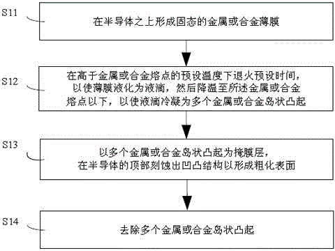
The invention provides a semiconductor layer surface roughening method. The semiconductor layer surface roughening method comprises steps: a semiconductor layer is provided, and the semiconductor layer is a nitride semiconductor layer; a solid metal or alloy film is formed on the semiconductor layer; annealing is carried out for preset time at a preset temperature higher than the melting point of the metal or the alloy thus the metal or alloy film is liquefied into a plurality of metal or alloy liquid drops, then the temperature is lowered to a temperature lower than the melting point of the metal or the alloy, thus the plurality of metal or alloy liquid drops are condensed into a plurality of metal or alloy island-shaped projections; the plurality of metal or alloy island-shaped projections are employed as a mask layer, and a concave-convex structure is etched on the layer top surface of the semiconductor and a roughed surface is formed; the plurality of metal or alloy island-shaped projections are removed. The semiconductor layer surface roughening method is advantageous in that the uniformity is good, and the method is stable and reliable. The invention also provides a formation method for an LED structure with a roughened surface.

Description

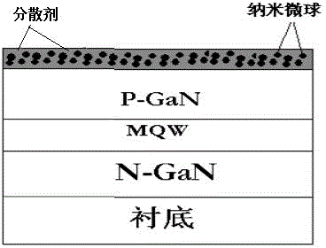
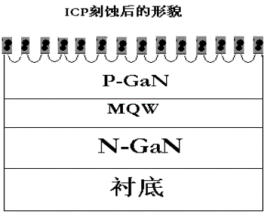
technical field [0001] The invention belongs to the technical field of semiconductors, and in particular relates to a method for roughening the surface of a semiconductor layer and a method for forming an LED structure with surface roughening. Background technique [0002] Studies have shown that roughening the surface of a GaN-based LED chip can improve its external quantum efficiency and increase the light efficiency of the chip. The existing conventional process is the nano-microsphere mask etching method. The process is as follows: firstly, epitaxial layers are respectively deposited on the sapphire substrate material: from bottom to top, there are buffer layer, N-type GaN layer, MQW light-emitting layer, and P-type GaN layer. GaN layer; secondly, a dispersant mixed with uniform nanospheres is spin-coated on the P-type GaN layer, such as Figure 1a As shown; then roughening is formed by etching technology, in which the role of nano-microspheres is to block ICP etching, a...

Claims


Application Information

Patent Timeline
Patent Type & Authority Applications(China)
IPC IPC(8): H01L33/22H01L33/00
Inventor 张杰彭遥
Owner HUIZHOU BYD IND
Learn More