
Oscillation circuit, current generation circuit, and oscillation method

An oscillation circuit and current technology, applied in power oscillators, pulse generation, electrical components, etc., can solve the problems of increased layout area and increased number of components, and achieve the effect of suppressing the increase in layout area and temperature dependence.

Active Publication Date: 2015-11-25
LAPIS SEMICON CO LTD
View PDF14 Cites 0 Cited by
  • Summary
  • Abstract
  • Description
  • Claims
  • Application Information

AI Technical Summary

Problems solved by technology

In addition, since a dedicated bandgap circuit, multiple operational amplifiers, and high withstand voltage MOS transistors need to be used, there are problems such as an increase in the number of components and an increase in the layout area.

Method used


Image

  • Oscillation circuit, current generation circuit, and oscillation method
  • Oscillation circuit, current generation circuit, and oscillation method
  • Oscillation circuit, current generation circuit, and oscillation method

Examples


no. 1 approach

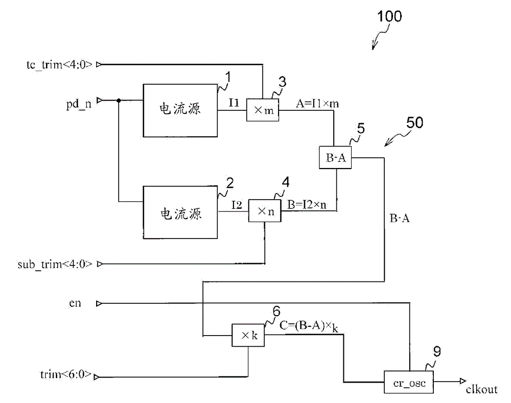
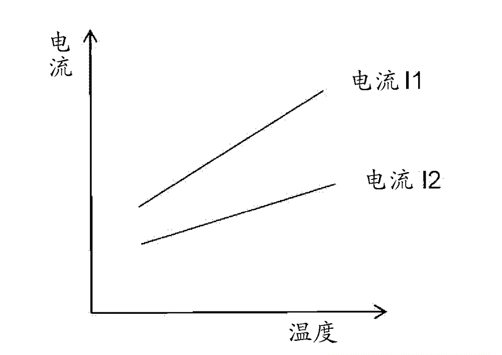
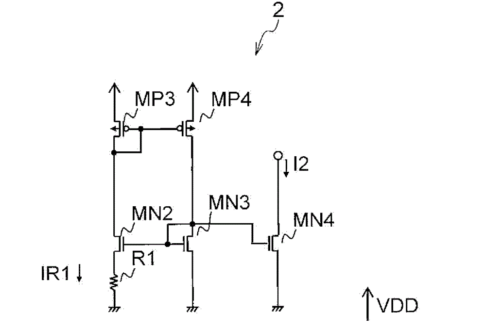
[0032] refer to Figure 1 to Figure 7 , the oscillation circuit 100 and the current generating circuit 50 of this embodiment will be described. figure 1 is a functional block diagram showing the oscillation circuit of this embodiment, Figure 2 to Figure 4 and Figure 7 are shown respectively figure 1 The specific circuits of the current source 1, the current source 2, the subtraction circuit 5, and the clock generation circuit 9. also, Figure 5 is a graph for explaining the temperature dependence of the current source 1 and the current source 2 of the present embodiment, Figure 6 It is a graph for explaining suppression of the temperature dependence of the current source 1 and the current source 2 of this embodiment.

[0033] Such as figure 1 As shown, the oscillation circuit 100 of this embodiment includes a current source 1, a current source 2, and trimming circuits 3, 4, 6 (in figure 1 , respectively recorded as ×m, ×n, ×k), subtraction circuit 5 (in figure 1 , r...

no. 2 approach

[0071] refer to Figure 8 and Figure 9 The oscillation circuit 200 of this embodiment will be described. Such as Figure 8 As shown, the oscillator circuit 200 is the figure 1 In the illustrated oscillation circuit 100 , the current source 1 is replaced with a current source 1 a, and the current generation circuit 50 is replaced with an oscillation circuit of a current generation circuit 50 a. Therefore, the same reference numerals are attached to the same configurations, and descriptions thereof are omitted.

[0072] exist image 3 In the current source 2 shown, when the element temperature is high, for example, 100°C or higher, the leakage current component increases exponentially. Therefore, there is a problem that the leakage component remains even when the difference from the current source 1 is taken. , the charging current of capacitors C0 and C1 increases due to high temperature, and the oscillation frequency becomes higher. The current generating circuit 50a an...


PUM


Abstract

The present invention provides an oscillation circuit including: a first current source having dependency of current value / temperature exhibiting a first characteristic; a second current source having dependency of current value / temperature exhibiting a second characteristic; a first conversion section, input with a current from the first current source, that outputs a first current having a specific characteristic which is converted from the first characteristic; a second conversion section, input with a current from the second current source, that outputs a second current having a specific characteristic which is converted from the second characteristic; a subtraction section, input with the first and the second current, that outputs a difference current that is a difference between the first and the second current; and a clock generation section that generates a clock signal by alternately charging and discharging a first and a second capacitor based on the difference current.

Description

technical field [0001] The present invention relates to an oscillating circuit, a current generating circuit, and an oscillating method. Background technique [0002] One of the main parameters in designing an oscillation circuit is the frequency accuracy of the clock output from the oscillation circuit. In order to improve the frequency accuracy of the output clock, it is required to use a reference current generation circuit used inside the oscillation circuit. The temperature dependence of the situation is reduced. [0003] Paragraphs [0019]-[0036] of Patent Document 1, figure 1 The disclosed oscillator circuit. The oscillating circuit 1 disclosed in Patent Document 1 is particularly an oscillating circuit built in a microcontroller, and includes: a reference resistor RE1 generating a reference current, an operational amplifier AMP1 supplying current to the reference resistor RE1, and a reference voltage applied to the reference resistor RE1. The reference voltage gene...

Claims


Application Information

Patent Timeline
Patent Type & Authority Applications(China)
IPC IPC(8): H03B5/04
CPCH03B5/04H03K3/0231H03K3/011
Inventor 御手洗睦
Owner LAPIS SEMICON CO LTD
Learn More