
Remote video image transmission system

A technology of transmission system and remote video, applied in the direction of closed-circuit television system, etc., can solve the problems of large size of signal collector, no integration of remote signal collector, and insufficient image clarity.

Inactive Publication Date: 2015-11-25
WUHU HANGFEI SCI & TECH
View PDF0 Cites 0 Cited by
  • Summary
  • Abstract
  • Description
  • Claims
  • Application Information

AI Technical Summary

Problems solved by technology

[0004] However, most of the transmission systems in the prior art are not integrated with remote signal collectors, and most of the existing signal collectors used in a remote video image transmission system are too large in size, and the imaging is not clear enough and many other deficiencies and defects

Method used


Image

  • Remote video image transmission system
  • Remote video image transmission system
  • Remote video image transmission system

Examples


Embodiment Construction

[0012] In order to make the technical means, creative features, goals and effects achieved by the present invention easy to understand, the present invention will be further described below in conjunction with specific illustrations.

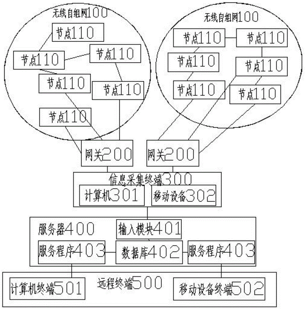
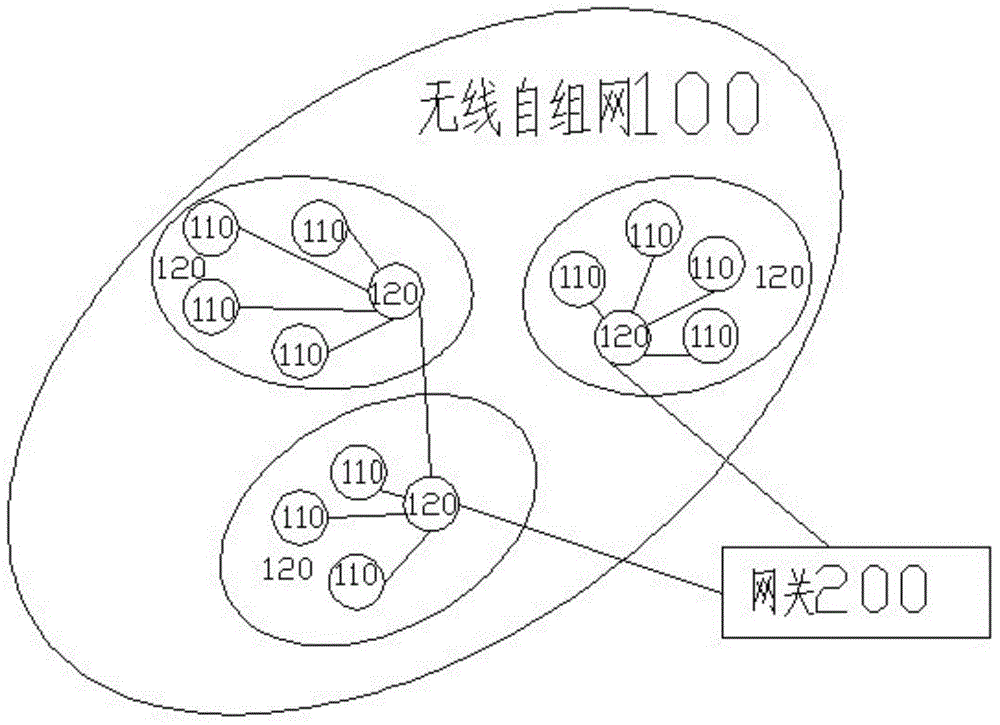
[0013] Such as figure 1 As shown, a remote video image transmission system according to the present invention is provided with several wireless ad hoc networks 100 to monitor different environmental areas; each wireless ad hoc network 100 regularly sends data to the information collection terminal 300 through the gateway 200, The information collection terminal 300 collects and uploads the monitoring data of the region to the server 400 for storage; the user can access the server 400 through the client 500 to query real-time or historical environmental data of all regions.

[0014] Cooperate see figure 1 , each wireless ad hoc network 100 includes a number of nodes 110, which is the most basic part of the entire remote video image transmission ...


PUM


Abstract

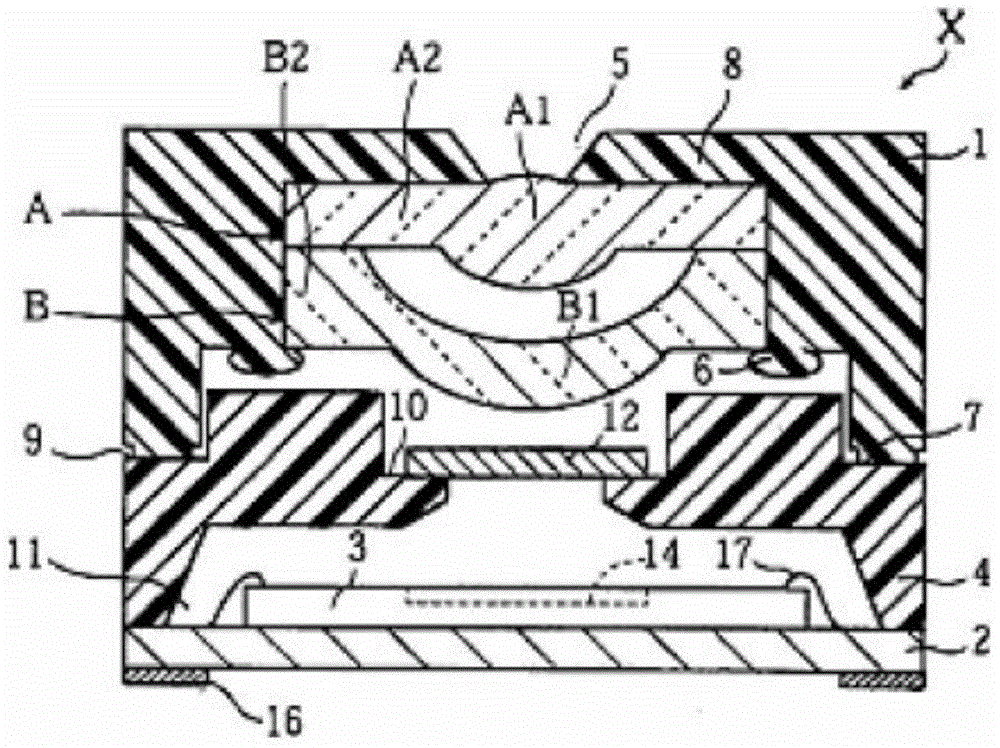
The invention relates to a remote video image transmission system. The remote video image transmission system comprises wireless self-organized networks; each self-organized network comprises a plurality of nodes; each node is provided with a signal collector; video data collected by the signal collector is transmitted to a user side through a wired and / or wireless network; the remote video image transmission system is characterized in that the signal collector sequentially comprises a biconvex lens, a convex lens and an image sensing chip, wherein the focal length of the biconvex lens is f1; the focal length of the convex lens is f2; the image sensing chip is used for receiving an image; the f1 / f2 ratio is between minus 0.2 and minus 0.8; and, if the focal length of an imaging system composed of the biconvex lens and the convex lens is f, the f1 / f ratio is within 1.25-2.5.

Description

technical field [0001] The invention relates to the technical field of image transmission, in particular to a remote video image transmission system. Background technique [0002] A remote video image transmission system is widely used in the field of information technology. Patent document W099 / 23833AI discloses a new type of remote video image transmission system for maintaining timing synchronization in digital video networks and digital video and data transmission systems. Enables transmission of digital video content such as Internet data, plain old telephone service (POTS), two-way data services to end users over the communication channel. The channel is usually a pair of copper wires running between the telephone company central office and the customer's premises, but can be any communication medium that supports compressed digital video, bi-directional data such as Internet data and POTS communication, and in fact can be a wireless connection. Digital video and data...

Claims


Application Information

Patent Timeline
Patent Type & Authority Applications(China)
IPC IPC(8): H04N7/18
Inventor 宋琪陈之典罗诗旭王宇航檀剑飞汪言康陈坤朱倩邓禹
Owner WUHU HANGFEI SCI & TECH
Learn More