Powder de-ironing separator

An iron remover and powder technology, which is applied in chemical instruments and methods, magnetic separation, solid separation, etc., can solve the problems of troublesome cleaning, damage to equipment, threats to food and drug safety, etc., so as to reduce manual labor and improve iron removal efficiency. , Improve the effect of screening quality

Inactive Publication Date: 2015-12-02
XINXIANG ZHEN YING MACHINERY EQUIP CO LTD
View PDF10 Cites 6 Cited by
  • Summary
  • Abstract
  • Description
  • Claims
  • Application Information

AI Technical Summary

Problems solved by technology

[0002] In the production process of existing products using dry powder as raw material, especially in the food and drug industry, the raw material dry powder generally needs to be processed and screened before use. In order to ensure the quality of the product, it is necessary to remove the impurities of the raw material, especially the hard Iron powder and iron filings, these hard impurities not only seriously threaten food and drug safety, but also cause damage to equipment. Therefore, iron removal equipment must be used to remove iron from raw materials
[0003] At present, the most widely used iron removal equipment is the iron remover made of permanent magnets. Its advantages are: simple and practical structure, economical, safe and reliable. However, when the permanent magnets of the iron remover absorb more and more magnetic substances, it is necessary to To remove the adsorbed iron powder and iron filings from the surface of the magnet, it is necessary to manually take out the magnet, which is troublesome to clean

Method used


Image

  • Powder de-ironing separator
  • Powder de-ironing separator
  • Powder de-ironing separator

Examples


Embodiment Construction

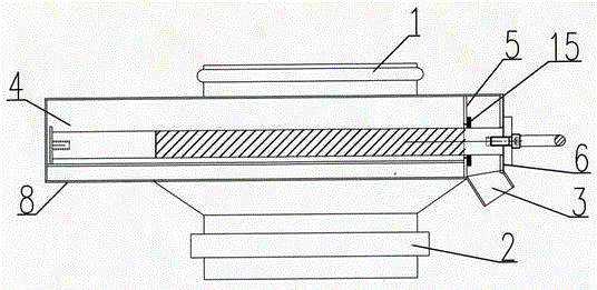
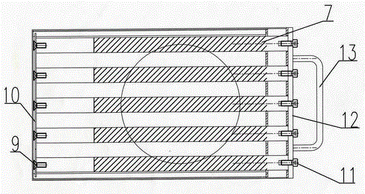
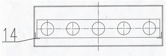
[0009] Describe embodiment in detail in conjunction with above accompanying drawing, see figure 1 As shown, the upper part of the iron remover box 4 is provided with a feed port 1, and its lower part is provided with a discharge port 2, and one end of the lower part of the iron remover box is provided with an iron discharge port 3, and the longitudinal position of the iron remover box inner cavity is used The partition 5 is divided into an iron-absorbing area and an iron-unloading area. The partition 5 is provided with a round hole for the magnetic bar 7 to pass through. There are multiple round holes. There is a horizontal guide rail 14 for the magnetic frame 8 to slide, the magnetic frame is a rectangular frame made of a magnetic bar front fixed plate 10 and a magnetic bar rear fixed plate 12, and a magnetic bar 7 fixed thereon, and the magnetic bar It is fixed on the front fixing plate 12 of the magnetic bar through the hexagonal socket head screw 11, the magnetic bar passe...


PUM


Abstract

The invention discloses a powder de-ironing separator. A feed opening is formed in the upper part of the de-ironing separator box body, and a discharge opening is formed in the lower part of the de-ironing separator box body; an iron discharge opening is formed in the side surface of lower part of the de-ironing separator box body; the inner chamber of the de-ironing separator is divided into an iron absorbing area and an iron unloading area using a separating plate at the longitudinal position; round holes allowing magnetic bars to penetrate through are formed in the separating plate; guide rails enabling a magnetic frame to slide are arranged on the two side walls of the inner chamber of the de-ironing separator box body in the horizontal direction; the magnetic frame is composed of a magnetic bar front fixing plate, a magnetic bar rear fixing plate, and the magnetic bars; a non-magnetic zone is arranged at the tail ends of the magnetic bars; one end of each magnetic bar is fixed to the magnetic bar front fixing plate through screws, and the other end of each magnetic bar penetrates through the round hole formed in the separating plate and is fixed to the magnetic bar rear fixing plate through a fastener; the end, positioned at the iron unloading area, of each magnetic bar penetrates through a rubber plate with a round hole; a magnetic frame handle is mounted on the magnetic bar front fixing plate. The technical scheme provided by the invention can be used to conveniently remove the powdered iron and iron scraps on the surface of the permanent magnetic de-ironing separator, improve the screening quality of the dry powder, reduce labor work, and meanwhile improve the iron removal efficiency.

Description

Technical field: [0001] The invention relates to a powder iron remover, which is especially suitable for screening dry powder, especially raw materials in the food and drug industry. Background technique: [0002] In the production process of existing products using dry powder as raw material, especially in the food and drug industry, the raw material dry powder generally needs to be processed and screened before use. In order to ensure the quality of the product, it is necessary to remove the impurities of the raw material, especially the hard Iron powder and iron filings, these hard impurities not only seriously threaten food and drug safety, but also cause damage to equipment. Therefore, iron removal equipment must be used to remove iron from raw materials. [0003] At present, the most widely used iron removal equipment is the iron remover made of permanent magnets. Its advantages are: simple and practical structure, economical, safe and reliable. However, when the perma...

Claims


Application Information

Patent Timeline
Patent Type & Authority Applications(China)
IPC IPC(8): B03C1/04B03C1/02
Inventor 秦英
Owner XINXIANG ZHEN YING MACHINERY EQUIP CO LTD
Why Eureka
Try Eureka