
A Die for Machining Precision Switching Elements Convenient for Chip Removal

A switching element and mold technology, applied in the field of machining, can solve the problems of unreasonable design of chip removal system, complex process, poor quality of finished products, etc., and achieve the effects of simple structure, good safety and convenient operation.

Active Publication Date: 2016-07-06
JINGDE HUAFENG ELECTRONICS COMPONENT
View PDF7 Cites 0 Cited by
  • Summary
  • Abstract
  • Description
  • Claims
  • Application Information

AI Technical Summary

Problems solved by technology

However, the existing production and processing generally adopt stamping forming, the process is relatively complicated, the quality of the finished product is not good, and the equipment cost is high and the production efficiency is low.
Moreover, when the problem is more difficult to solve, when the mold is processing parts, it is easy to be blocked by waste chips, and the design of the chip removal system has always been very unreasonable.

Method used


Image

  • A Die for Machining Precision Switching Elements Convenient for Chip Removal
  • A Die for Machining Precision Switching Elements Convenient for Chip Removal
  • A Die for Machining Precision Switching Elements Convenient for Chip Removal

Examples


Embodiment Construction

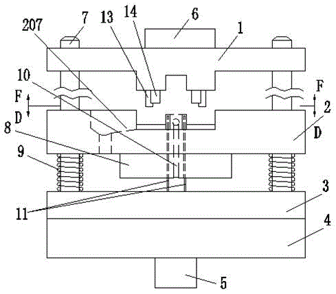
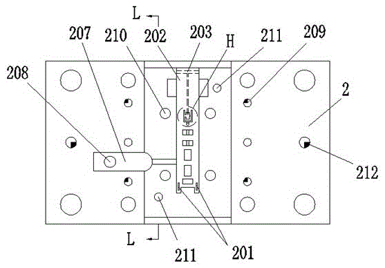
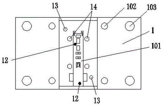
[0025] Such as Figure 1 to Figure 6 As shown, a mold for processing precision switch elements that is convenient for chip removal includes an upper template 1, a lower template 2, a support plate 4 and an electric pressure device 6 arranged on the upper template 1 for providing punching power downward, for When forming parts for this set of molds, it provides a power source with very high productivity.

[0026] Such as figure 2 and Figure 6 As shown, the lower template 2 is a cuboid structure, with a groove in the middle, and the groove is arranged as a V-shaped inclined surface 213; bosses 214 are arranged at both ends of the groove; a punch 202 is arranged in the groove; Figure 4 As shown, the middle molding part of the punch 202 is provided with a special-shaped groove 204, and the inside of the special-shaped groove 204 is processed with a vertical connection hole 1 205, and the outside is provided with a horizontal connection hole 2 206; the punch 202 There is also...


PUM


Abstract

The invention discloses a precise switch element processing die convenient for chip removal, and relates to the technical field of machining. The precise switch element processing die comprises an upper die plate, a lower die plate, a support plate and an electric pressure device which is arranged on the upper die plate and used for downwards supplying stamping power; one-time high-speed batch production of precise switch elements can be performed through a cooling system and a chip removal system which are arranged on the upper die plate and the lower die plate. The precise switch element processing die is simple and practical in structure, convenient to operate, very good in safety and capable of adequately solving the problem of difficult chip removal in the die, reducing the failure rate of equipment production, improving the production efficiency, and lowering the cost.

Description

technical field [0001] The invention relates to the technical field of mechanical processing, in particular to a mold for processing precision switch elements which is convenient for chip removal. Background technique [0002] Mold (mújù), various molds and tools used in industrial production for injection molding, blow molding, extrusion, die-casting or forging forming, smelting, stamping and other methods to obtain the required products. In short, a mold is a tool used to shape an object. This tool is composed of various parts, and different molds are composed of different parts. It mainly realizes the processing of the shape of the article through the change of the physical state of the formed material. Known as the "Mother of Industry". Under the action of external force, the blank becomes a tool with a specific shape and size. Widely used in blanking, die forging, cold heading, extrusion, powder metallurgy parts pressing, pressure casting, and compression molding or ...

Claims


Application Information

Patent Timeline
Patent Type & Authority Patents(China)
IPC IPC(8): B21D37/10B21D45/00
Inventor 姚祚春
Owner JINGDE HUAFENG ELECTRONICS COMPONENT
Learn More