
Lightweight air chamber bracket of vehicle

A lightweight, air chamber technology, applied in the field of vehicles, can solve problems such as unreasonable structure and heavy weight, and achieve the effects of reducing machine cost, improving power performance, and reducing vehicle cost

Active Publication Date: 2015-12-02
HOUMA CITY ZHONGJIN MACHINERY
View PDF7 Cites 0 Cited by
  • Summary
  • Abstract
  • Description
  • Claims
  • Application Information

AI Technical Summary

Problems solved by technology

[0003] The object of the present invention is to provide a light-weight automobile air chamber support with light weight and reasonable structure in view of the defects of heavy weight and unreasonable structure in the automobile air chamber support in the above-mentioned existing design

Method used


Image

  • Lightweight air chamber bracket of vehicle
  • Lightweight air chamber bracket of vehicle
  • Lightweight air chamber bracket of vehicle

Examples


Embodiment 1

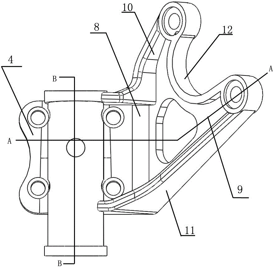
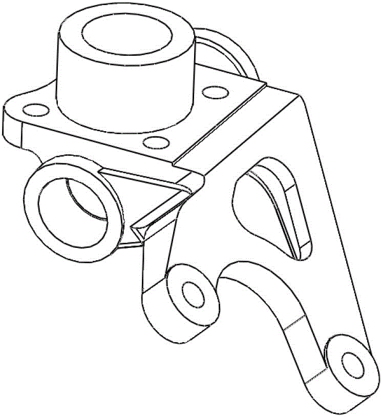
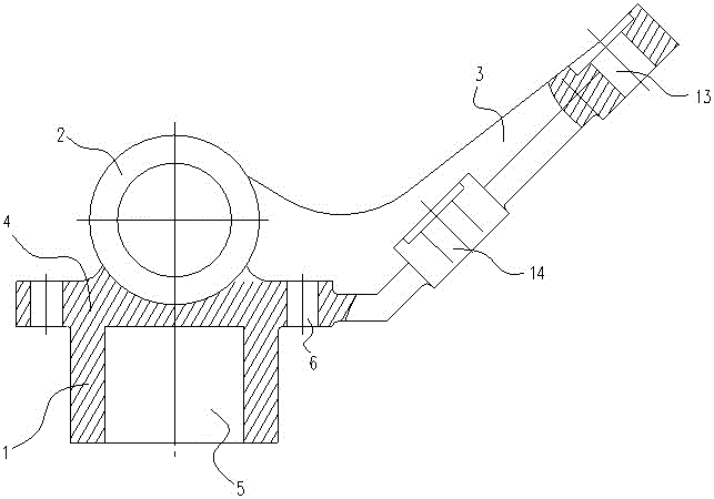
[0020] Such as figure 1 , 2 , Shown in 3 and 4, a light-weight air chamber support for automobiles, the air chamber support is integrally cast, and it includes a kingpin bearing seat 1, a camshaft bearing seat 2 and an air chamber mounting seat 3; the kingpin bearing seat 1 has A mounting part 4 for fixing the air chamber bracket and a hollow cylindrical part 5 arranged below the mounting part 4, the hollow cylindrical part 5 is used for installing the kingpin shaft, and an oil hole 16 is arranged on the cylindrical surface of the hollow cylindrical part 5 , the lower surface of the mounting part 4 is also provided with an air chamber bracket orientation pin hole 17 at a position close to the hollow cylindrical part 5, and 4 bolt holes 6 are provided on the mounting part 4; the camshaft bearing housing 2 has a hollow long cylindrical part 7. Set above the installation part 4, it is used to install the camshaft, and the connecting part between the installation part 4 and the c...

Embodiment 2

[0022] Such as figure 1 , 2 , Shown in 3 and 4, a light-weight air chamber support for automobiles, the air chamber support is integrally cast, and it includes a kingpin bearing seat 1, a camshaft bearing seat 2 and an air chamber mounting seat 3; the kingpin bearing seat 1 has A mounting part 4 for fixing the air chamber bracket and a hollow cylindrical part 5 arranged below the mounting part 4, the hollow cylindrical part 5 is used for installing the kingpin shaft, and an oil hole 16 is arranged on the cylindrical surface of the hollow cylindrical part 5 , the lower surface of the mounting part 4 is also provided with an air chamber bracket orientation pin hole 17 at a position close to the hollow cylindrical part 5, and 4 bolt holes 6 are provided on the mounting part 4; the camshaft bearing housing 2 has a hollow long cylindrical part 7. Set above the installation part 4, it is used to install the camshaft, and the connecting part between the installation part 4 and the c...


PUM


Abstract

The invention relates to a lightweight air chamber bracket of a vehicle. The air chamber bracket is integrally formed in a casting manner and comprises a main pin bearing seat, a camshaft bearing seat and an air chamber mounting seat, wherein the main pin bearing seat comprises a mounting part for fixing the air chamber bracket and a hollow cylinder part arranged under the mounting part, and four bolt holes are formed in the mounting part; the camshaft bearing seat comprises a hollow long cylinder part arranged above the mounting part, and connecting positions between the mounting part and the camshaft bearing seat are cast into a whole in a manner of transitional connection. According to the lightweight air chamber bracket disclosed by the invention, a hollow inner cavity is removed, cores used for casting are reduced, and the weight of a product is further lightened by 20%, so that the casting cost is reduced; besides through the lightweight air chamber bracket, lengths of connecting bolts are shortened by 2 / 3, so that the cost of parts is reduced; besides through the lightweight air chamber bracket, a machining cutting tool is saved, so that the machining cost is reduced, finally the weight of the complete vehicle is lightened, and the cost of the complete vehicle is reduced.

Description

technical field [0001] The invention relates to the field of vehicles, in particular to an automobile lightweight air chamber bracket. Background technique [0002] At present, the automobile air chamber brackets used in the market such as figure 1 As shown, the camshaft bearing seat of this air chamber bracket is designed as a closed structure with a hollow inner cavity. This closed structure not only increases the difficulty of casting and reduces the efficiency of casting molding, but also increases the cost of casting due to the increase in material and weight. The cost of casting and energy consumption is increased, and more importantly, the defect of the automobile air chamber bracket cast by this structure is very serious. Contents of the invention [0003] The object of the present invention is to provide a light-weight automobile air chamber support with reduced weight and reasonable structure, aiming at the defects of heavy weight and unreasonable structure in t...

Claims


Application Information

Patent Timeline
IPC IPC(8): B60T17/00
CPCB60T17/00
Inventor 王庆薛塬东宁涛王昊运郝春泉杨勇宁华
Owner HOUMA CITY ZHONGJIN MACHINERY
Learn More