Preparation process of high-strength hydrophobic ceramsite
A preparation process and hydrophobicity technology, which is applied in the field of recycling and reuse of industrial solid waste resources, can solve the problems of easy damage to the environment, poor purpose and strength of ceramsite, and high cost of raw materials, so as to reduce water absorption, increase density, and achieve good results Effect
- Summary
- Abstract
- Description
- Claims
- Application Information
AI Technical Summary
Problems solved by technology
Method used
Image
Examples
Embodiment 1
[0023] Embodiment 1: In the preparation process of high-strength hydrophobic ceramsite, the following steps are included:
[0024] (1) Raw material preparation: select the following ingredients according to the weight percentage for drying and crushing: 63% slag, 25% coal gangue, 7% fly ash, 5% clay powder, after primary stirring, pass through a 320 mesh sieve to form a particle size It is coarse powder less than 320 mesh and fine powder larger than 320 mesh. The slag is aluminum plant waste slag or aluminum sulfate plant waste slag, mainly Al 2 o 3 and SiO 2 Mainly, the waste slag from the aluminum plant or the waste slag from the aluminum sulfate plant as raw materials can meet the above-mentioned range of component distribution ratio.
[0025] (2) Secondary stirring: add MnO with a weight percentage of 2% to the coarse powder 2 and 5% TiO 2 , stir evenly; add the MnO that the weight percent content is 4% to the fine powder 2 , stir well.
[0026] (3) Granulation: Sen...
Embodiment 2
[0033] Embodiment 2: On the basis of the process of Embodiment 1, only one component in step (1) is modified, and the raw material composition by weight percentage in step (1) is optimized: slag 64%, coal gangue 23%, pulverized coal Ash 6%, clay powder 7%.
Embodiment 3
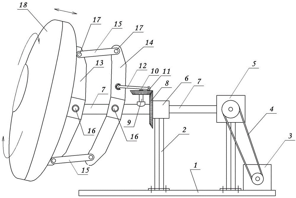
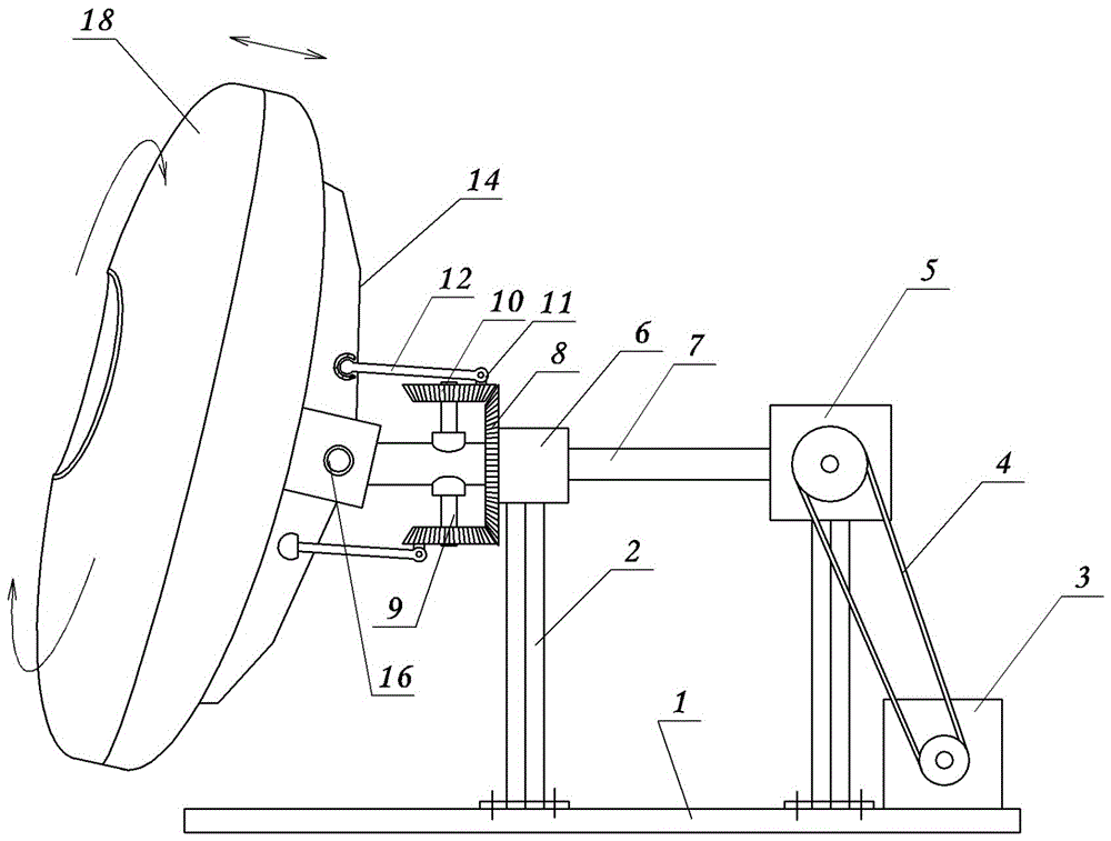
[0034] Embodiment 3: On the basis of the process of Embodiment 1, the following granulator structure is adopted. see figure 1 , a bracket 2 is set on the base 1, and a bearing seat 6 and a gearbox 5 are fixed on the bracket 2. The power shaft 7 is horizontally installed in the bearing seat 6, and the rear end of the power shaft 7 is connected with the output shaft of the gearbox 5 , the input shaft of the gear box 5 is connected to the power mechanism 3 through the transmission mechanism 4.
[0035]The front end of the power shaft 7 is connected with a ball-forming disc 18 . The specific structure is: a back support plate 13 is fixed on the back side of the ball forming disc 18, and one end of the power shaft 7 is hinged to the middle part of the back support plate 13 through the center shaft 16 (equivalent to being hinged at the center of the back of the ball forming disc 18 ). An auxiliary support plate 14 parallel to the rear side of the back support plate 13 is also arr...
PUM
 Abstract
Description
Claims
Application Information
 - R&D
- Intellectual Property
- Life Sciences
- Materials
- Tech Scout
- Unparalleled Data Quality
- Higher Quality Content
- 60% Fewer Hallucinations
Browse by: Latest US Patents, China's latest patents, Technical Efficacy Thesaurus, Application Domain, Technology Topic, Popular Technical Reports.
© 2025 PatSnap. All rights reserved.Legal|Privacy policy|Modern Slavery Act Transparency Statement|Sitemap|About US| Contact US: help@patsnap.com


