No-water floor heating system

A heating system and floor technology, which is applied in the field of anhydrous floor heating systems, can solve the problems of low energy utilization rate, large amount of underground pipe drilling works, excess heat supply, etc., so as to reduce dust and planktonic bacteria, and benefit the human body. Health, the effect of reducing the number of starts and stops

Inactive Publication Date: 2015-12-02
BEIJING ENPOWER SOLAR ENERGY IND
View PDF10 Cites 1 Cited by
  • Summary
  • Abstract
  • Description
  • Claims
  • Application Information

AI Technical Summary

Problems solved by technology

[0005] 1. Although the single coal-fired boiler heating system is simple in structure and reliable in operation, it has serious environmental pollution and will be phased out
[0006] 2. Solar heat collection and heating technology, the density of sunlight heat collection is low, and a large collector lighting area is required. Due to the change of weather, a large hot water storage tank is required. Because the heating cycle is short, winter supply often occurs. Insufficient heat, excess heat supply in summer, unable to achieve seasonal energy storage
[0007] 3. Although the solar energy inter-seasonal thermal storage heating system is also equipped with heat pumps, electricity, auxiliary heating, and refrigeration devices, the engineering volume of underground pipe drilling is relatively large, and it is also limited by regional geological conditions.
The heat released is not collected and utilized, so a certain degree of waste is caused, resulting in a low overall energy utilization rate;
[0008] 4. A single electric heater stores heat for heating, utilizes low-peak electricity at night, and saves peak-time electricity consumption to achieve the purpose of energy saving and "peak-shifting and valley-filling" of electricity, but many township residences cannot be implemented due to the limitation of power grid capacity increase

Method used


Image

  • No-water floor heating system

Examples


Embodiment Construction

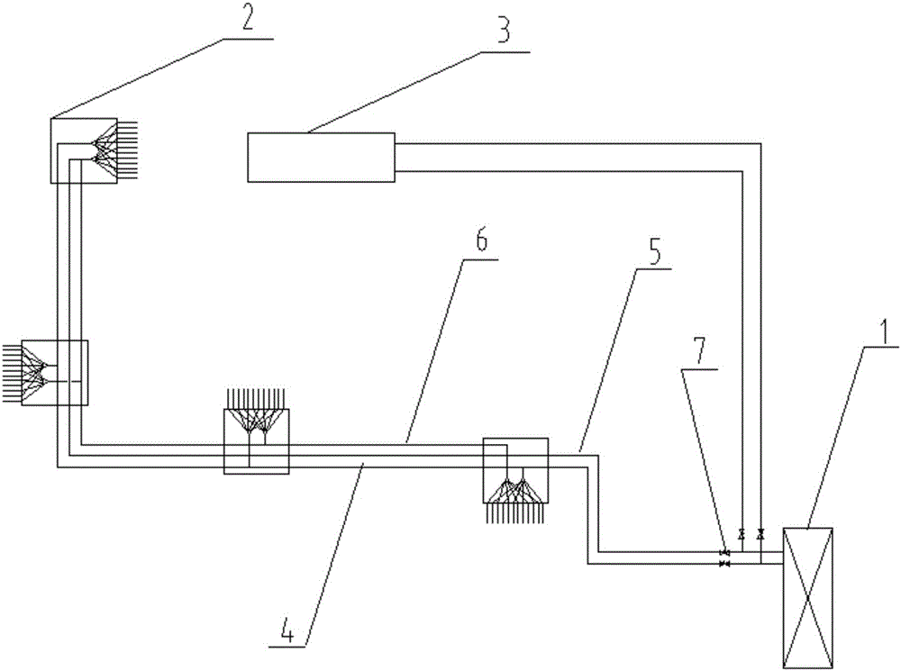
[0030] The present invention will be further described below in conjunction with the accompanying drawings and specific embodiments.

[0031] like figure 1 As shown, a waterless floor heating system includes an air source heat pump unit 1, an anhydrous floor system 2, a cold and hot fan air conditioning system 3 and an automatic control system (not shown in the figure), the air source heat pump unit 1, the waterless floor system The water floor system 2 and the hot and cold air-conditioning system 3 are respectively connected to the automatic control system. A main flow pipe 4 and a return flow pipe 5 are arranged between the air source heat pump unit 1 and the waterless floor system 2. The main flow pipe 4 and the The return pipe 5 is connected in the waterless floor system 2, the main flow pipe 4 and the return pipe 5 between the air source heat pump unit 1 and the waterless floor system 2 are provided with a reversing valve 7, and the air source heat pump The unit 1 can be...


PUM


Abstract

The invention belongs to the technical field of heating, and particularly relates to a no-water floor heating system. The no-water floor heating system comprises an air source heat pump unit, a no-water floor system, a cold and hot draught fan air conditioner system and an automatic control system. The air source heat pump unit, the no-water floor system and the cold and hot draught fan air conditioner system are all connected with the automatic control system. A main flow pipe and a backflow pipe are arranged between the air source heat pump unit and the no-water floor system and connected in the no-water floor system. The main flow pipe and the backflow pipe between the air source heat pump unit and the no-water floor system are each provided with a reversing valve. The air source heat pump unit can be switched into the cold and hot draught fan air conditioner system through the reversing valves. The no-water floor heating system is small in investment, low in energy consumption, simple in structure, low in cost, healthy and environmentally friendly.

Description

technical field [0001] The invention belongs to the technical field of heating, and in particular relates to a waterless floor heating system. Background technique [0002] With the rapid development of the economy and the continuous improvement of the living standards of urban residents, the energy consumption of building heating has also increased rapidly. At present, the heating energy consumption of cities and towns in northern China in winter accounts for about 40% of the total energy consumption of urban buildings in the country, and is the largest component of building energy consumption. Therefore, reducing building heating energy consumption is an important way to achieve energy conservation and emission reduction. [0003] The Chinese government and heating-related enterprises are actively promoting the household heat metering system for the central heating method of natural gas used by the government in the vast building areas of the city. However, in the process ...

Claims


Application Information

Patent Timeline
Patent Type & Authority Applications(China)
IPC IPC(8): F24D15/00F25B30/00
Inventor 于良许新中
Owner BEIJING ENPOWER SOLAR ENERGY IND
Why Eureka
Try Eureka