
Rotational centrifugal launcher

A technology of rotating centrifuge and launcher, which is applied in the direction of launching devices, space navigation equipment, space navigation ground equipment, etc. It can solve the problems of insufficient acceleration capability, low mass of projectiles, and difficulty in realization, and achieve low launch cost and small size , low-cost effect

Inactive Publication Date: 2015-12-02
陈云桥
View PDF6 Cites 13 Cited by
  • Summary
  • Abstract
  • Description
  • Claims
  • Application Information

AI Technical Summary

Problems solved by technology

However, this has to be at the expense of taking a longer orbit
Since the human body can only withstand a long-term acceleration of about 3 times the acceleration of gravity, in order to reach the first cosmic speed, the orbital length required for an electromagnetic device that meets the human body's tolerance needs to be about 1,000 kilometers, which is technically difficult to achieve
[0009] Second, the quality of shells that can be fired by electromagnetic guns is still low, which is caused by insufficient acceleration capabilities
[0011] As for the launch cost of the electromagnetic gun, in addition to the high-power power consumption, the cost of the ultra-low temperature liquid that generates a strong magnetic field must also be considered, and the cost is relatively high

Method used


Image

  • Rotational centrifugal launcher
  • Rotational centrifugal launcher
  • Rotational centrifugal launcher

Examples


Embodiment 1

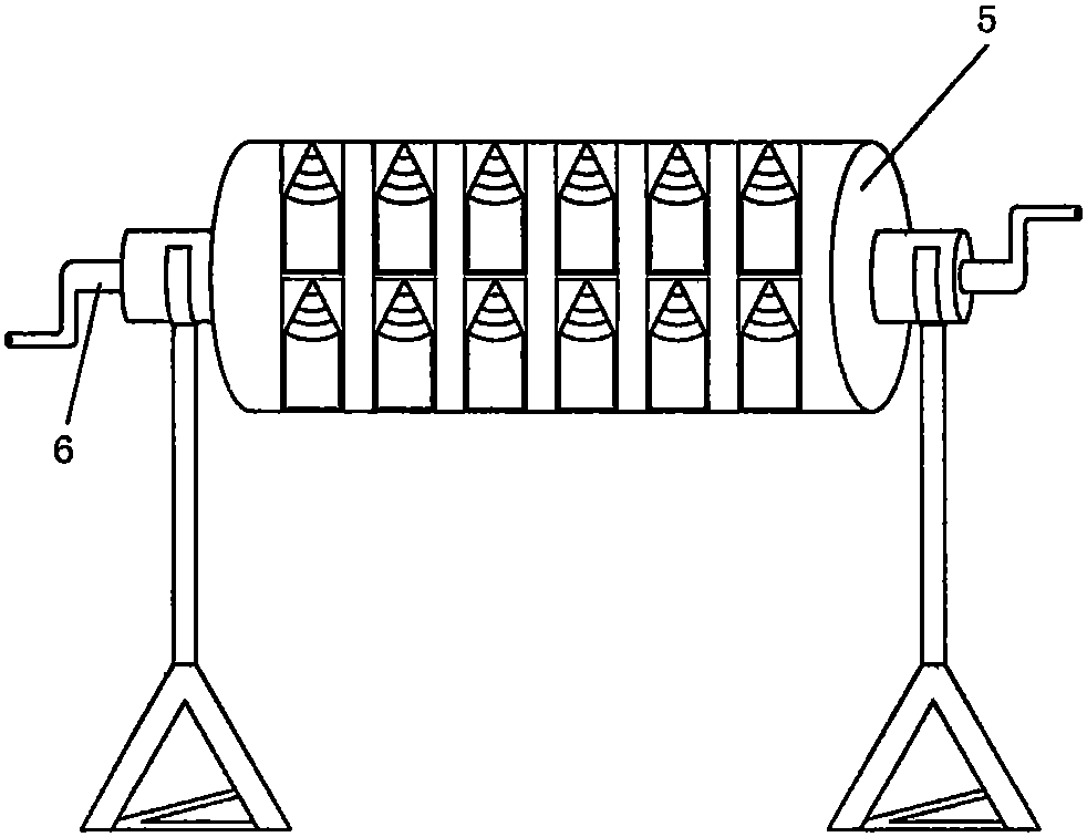
[0051] figure 2 It shows the structural diagram of the hand-operated projection device; according to the needs of lighter projectile weight and shorter projection distance, the present invention proposes an embodiment of a rotating centrifugal launcher with simple structure, which saves expensive motor and control variable speed The device directly replaces the driving device with the rocking handle 6, and the rotating device 5 is shaken by hand. According to the test, the object of several kilograms can also be launched several kilometers away, and the efficiency is also quite high.

Embodiment 2

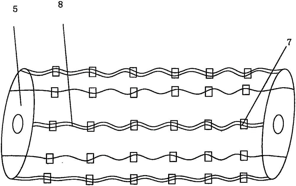
[0053]Embodiment 2 shows an electromagnetic release mechanism 7 of the present invention, image 3 Show the arrangement structure of the electromagnetic release device; Figure 4 It is a schematic diagram of the structure of the electromagnetic release device. The electromagnetic release mechanism 7 is arranged according to the arrangement of the launch tubes 16 , and is arranged at the tail of each launch tube 16 , and each electromagnetic release mechanism 7 is connected to the control device 3 by a wire 8 .

[0054] Described electromagnetic releasing mechanism 7 comprises electromagnet, strong spring 12 and friction plate 9, and wherein, the iron core 10 of electromagnet is hollow shape, and coil 11 is set in the iron core 10, and the space in the middle of iron core 10 is set strong spring 12, Powerful spring 12 is stage clip, is positioned between electromagnet end cover 13 and the armature 14 of electromagnet, and the other side of armature 14 is riveted friction plate...


PUM


Abstract

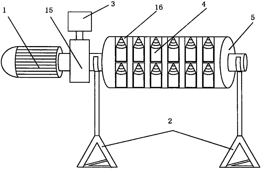
The invention discloses a rotational centrifugal launcher which comprises a power device, a control device, an accelerator and a base. The power device is composed of a driving motor (1) and a speed changing mechanism (15); the control device (3) adopts a single chip microcomputer or a computer to control the speed changing mechanism (15) and the launching initial speeds and launching angles of launching objects (4); the accelerator comprises a rotating device (5), multiple launching canisters (16) and electromagnetic releasing mechanisms (7), the launching canisters (16) are fixed on the edge of the whole circumference of the rotating device (5) and driven by the power device to rotate to reach certain revolutions, and therefore the launching objects (4) in the launching canisters (16) can acquire certain initial speed and kinetic energy. The rotational centrifugal launcher is small in size and weight and high in invisibility and launching precision, one launcher can launch warheads of different warhead diameters, and single launching, continuous launching and mass launching can be all achieved; heavy objects can be safely sent to the far place at low cost, even the outer space.

Description

technical field [0001] The invention relates to a centrifugal device, in particular to a device for projecting heavy objects by using centrifugal force, which is used in the fields of weaponry and space launch. Background technique [0002] To launch objects or heavy objects at a certain initial velocity, such as launching bullets or shells, and launching spaceships into space orbits, the current method is to rely on chemical fuel combustion to obtain kinetic energy to propel objects into orbit; but the chemical fuel combustion process In the process, a large amount of heat energy and sound will be released, and the energy loss will be large. Basically, the conversion efficiency of these fuels is not high. [0003] Generally, the initial velocity of a bullet ejecting from the chamber is 300 meters per second. The speed when the artillery ejects from the chamber depends on the caliber and the length-to-diameter ratio of the gun barrel. The higher the height, of course, there...

Claims


Application Information

Patent Timeline
IPC IPC(8): F41F7/00B64G5/00
Inventor 陈云桥
Owner 陈云桥
Learn More