
Non-contact wheel multi-function detection system

A detection system and multi-functional technology, applied in measurement devices, instruments, optical devices, etc., can solve problems such as slow test speed, low test efficiency, and difficulty in online detection, and achieve improved test speed, data traceability, and ease of use. replacement effect

Active Publication Date: 2018-02-23
浙江欧星环美汽车部件有限公司
View PDF13 Cites 0 Cited by
  • Summary
  • Abstract
  • Description
  • Claims
  • Application Information

AI Technical Summary

Problems solved by technology

[0002] For the measurement of wheels, the existing technology has various test methods and various test equipment, such as "a wheel detection device" (patent No. CN201410577641.3), "wheel rim runout detection device" (patent No. CN201410660869.9), "Improved hub detection device" (Patent No. CN201310654210.8), "Steel ring rim runout detection process and equipment structure" (Patent No. CN200810121548.6), "Determination of rim geometry and installation Method and equipment for dismantling tires" (patent number CN200710194611.4), "a method and equipment for determining the geometric dimensions of motor vehicle wheels (rim tire assembly) through non-contact detection" (patent number CN200810128017.X), etc. Public technology, but most of the existing technologies including the above-mentioned public technology are laboratory measurements on wheels to obtain research data and pursue higher test accuracy, but there are defects of slow test speed and low test efficiency. Synchronized with the production beat on the production line, it is difficult to achieve online detection
In addition, the quality requirements of modern automobiles are constantly improving, and it is necessary to trace the online production data. The existing production line lacks online testing, which makes it difficult to meet higher requirements; and the products are shipped out of the production line and sent to the test area for testing. The method of returning to the production line is slow and inefficient, and it is difficult to meet the needs of high-speed and efficient production

Method used


Image

  • Non-contact wheel multi-function detection system
  • Non-contact wheel multi-function detection system
  • Non-contact wheel multi-function detection system

Examples


Embodiment

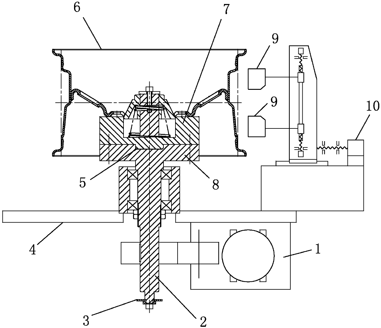
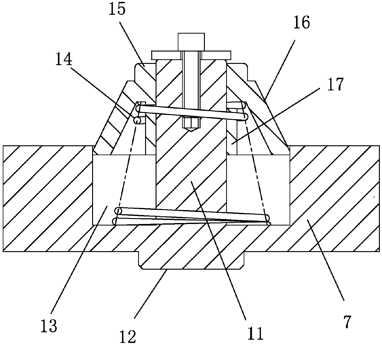
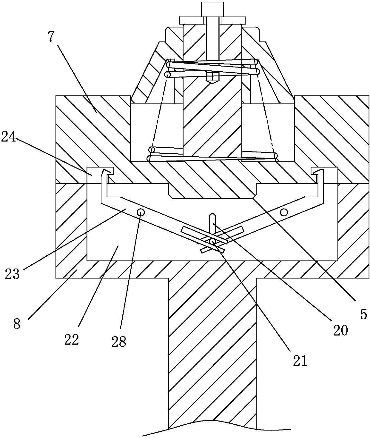
[0023] Example: the non-contact wheel multi-function detection system of the present invention, as attached figure 1 , attached figure 2 As shown, it includes a control system, a detection system, a data processing system, a shaft drive device 1 and a rotating shaft 2 driven by the shaft drive device 1. The rotating shaft 2 is sleeved with two tapered roller bearings, and the outer rings of the two tapered roller bearings are sleeved with bearings. The bearing seat is fixedly connected to the test bench body 4 .

[0024] The rotating shaft 2 is arranged vertically, a round table 8 is set at the top, and a test table 7 is connected to the round table 8; There is a vertical column 11 in the middle, and the vertical column 11 is sleeved with a conical table 15 that slides up and down along the vertical column 11. The conical table 15, the vertical column 11 and the rotating shaft 2 are arranged coaxially; the diameter of the top of the conical table 15 is smaller than the cente...


PUM


Abstract

The invention relates to a non-contact wheel multifunctional detection system, which includes a control system, a detection system, a data processing system, a shaft drive device and a rotating shaft, and is characterized in that: the rotating shaft is vertically arranged, a round platform is arranged at the top, and a test platform is connected to the round platform; The top of the platform is a plane adapted to the mounting surface of the wheel to be tested. A circular groove is arranged on the plane, and a column is arranged in the circular groove. The column is covered with a conical platform that slides up and down along the column. The rotating shafts are set coaxially; the diameter of the top of the conical table is smaller than the diameter of the center hole of the wheel to be tested, and the diameter of the bottom is larger than the diameter of the center hole of the wheel to be tested; a spring is set between the tapered table and the bottom surface of the circular groove; the detection system includes a horizontally movable and a vertically moving laser ranging sensor. The positioning, installation and dismounting of the wheels to be tested is simple and fast. The test bench can be easily replaced to test wheels of different specifications.

Description

technical field [0001] The invention relates to a testing device, in particular to a non-contact wheel multifunctional detection system for testing wheels online. Background technique [0002] For wheel measurement, the prior art has various testing methods and various testing equipment, such as "a wheel detection device" (Patent No. CN201410577641.3), "wheel rim runout detection device" (Patent No. CN201410577641.3) No. CN201410660869.9), "Improved wheel hub detection device" (patent number CN201310654210.8), "steel rim runout detection process and structure of equipment" (patent number CN200810121548.6), "determination of rim geometry and installation or A method and device for disassembling a tire" (Patent No. CN200710194611.4), "A method and device for determining the geometric dimensions of a motor vehicle wheel (rim tire assembly) through non-contact detection" (Patent No. CN200810128017.X), etc. However, most of the existing technologies, including the above-mentione...

Claims


Application Information

Patent Timeline
Patent Type & Authority Patents(China)
IPC IPC(8): G01B11/00G01B11/02G01B11/08G01B11/30
Inventor 孙小明熊红兵
Owner 浙江欧星环美汽车部件有限公司
Learn More