Ultrasound vector flow imaging (VFI) with curve tracing

A technology of vector flow and imaging, applied in ultrasonic/sonic/infrasonic image/data processing, radio wave measurement system, ultrasonic/sonic/infrasonic diagnosis, etc., can solve complex and heavy problems

Active Publication Date: 2015-12-02
B K MEDICAL
View PDF8 Cites 2 Cited by
  • Summary
  • Abstract
  • Description
  • Claims
  • Application Information

AI Technical Summary

Problems solved by technology

[0007] Unfortunately, the above process using B-mode, CFM-mode

Method used


Image

  • Ultrasound vector flow imaging (VFI) with curve tracing
  • Ultrasound vector flow imaging (VFI) with curve tracing
  • Ultrasound vector flow imaging (VFI) with curve tracing

Examples


Embodiment Construction

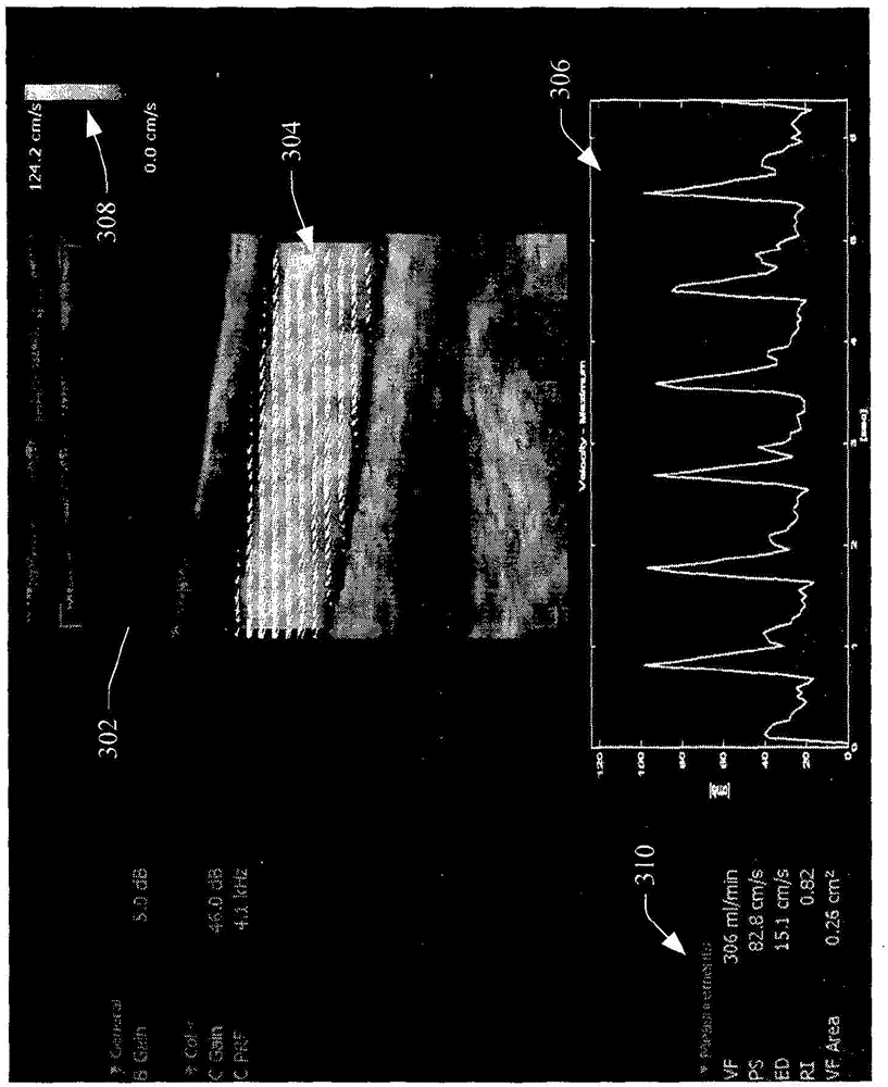
[0023] The following describes an approach for ultrasound VFI imaging with automatic curve tracing. In one instance, this approach provides direct visualization of the general nature of blood flow and automatically calculates velocity and / or volumetric flow trace information, thus reducing the use of spectral Doppler to determine such information, which simplifies user interaction with Scanner interaction.

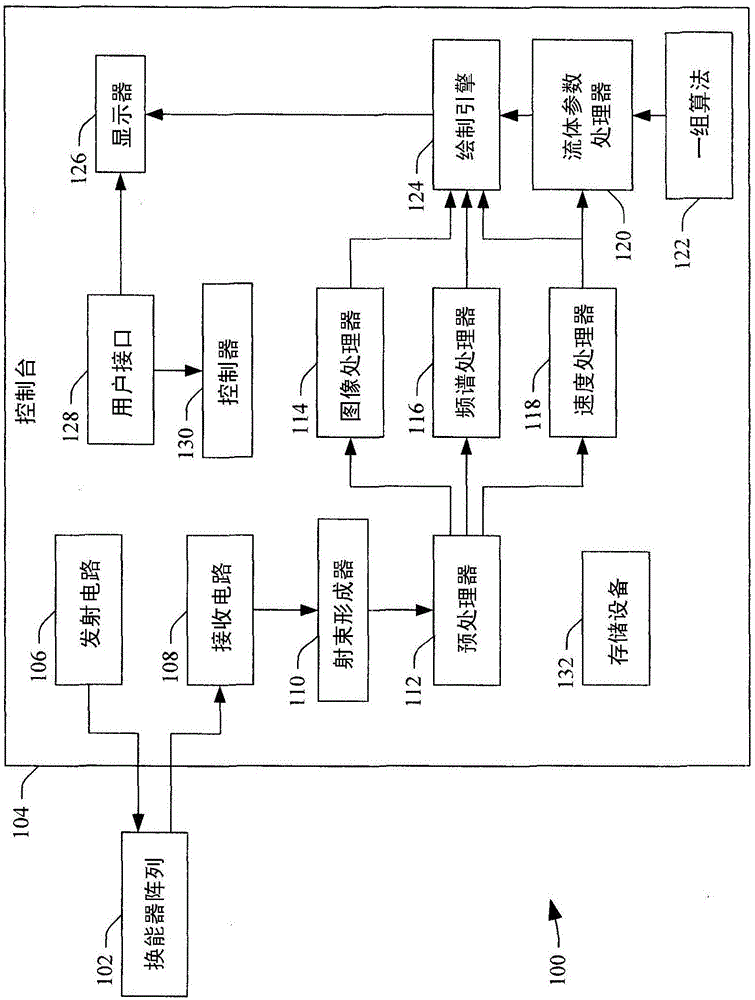
[0024] figure 1 An example ultrasound imaging system 100 is schematically illustrated. System 100 includes transducer array 102 interfaced with console 104 via a suitable wired and / or wireless interface.

[0025] The transducer array 102 converts electrical signals into an ultrasonic pressure field and vice versa. More specifically, the transducer array 102 includes an array of one or more transducer elements configured to transmit ultrasound signals and receive echo signals. Examples of suitable arrays include 128, 192, and / or other element arrays, including rectangu...


PUM


Abstract

An ultrasound imaging system (100) includes a velocity processor (118) that processes ultrasound data representing structure flowing through a tubular object and generates vector flow imaging information indicative of the structure flowing through a tubular object based thereon. The vector flow imaging information includes an axial velocity component signal and a lateral component signal, and the axial and lateral component signals indicate a direction and a speed of the structure flowing through the tubular object. The ultrasound imaging system further includes a flow parameter processor (120) that determines at least one flow parameter based on the vector flow imaging information and generates a signal indicative thereof.

Description

technical field [0001] The following relates generally to ultrasound imaging, and more specifically to a type of ultrasound velocity flow imaging (VFI) with curve tracing. Background technique [0002] Color Flow Mapping (CFM) is a means of estimating and visualizing intravascular blood flow in a combined B and CFM duplex mode. CFM images cover the full field of view equivalent to B-mode images, or the user uses the ultrasound system's Graphical User Interface (GUI) to place a box to indicate a region of interest (ROI). Unfortunately, CFM only shows relative flow information of whether blood flow is towards or away from the transducer. Therefore, it cannot show absolute flow direction or absolute velocity. [0003] To obtain quantitative information about blood flow, spectral Doppler (D) imaging has been used together with B-mode and CFM imaging. Typically, spectral Doppler imaging displays information about the power spectral density of received blood flow Doppler shift ...

Claims


Application Information

Patent Timeline
IPC IPC(8): A61B8/06A61B8/00A61B8/08
CPCA61B8/06A61B8/0891A61B8/463A61B8/5223G01S15/8984G16H50/30A61B8/065A61B8/145A61B8/4483A61B8/469A61B8/5207
Inventor P·豪高G·塞鲁普
Owner B K MEDICAL
Why Eureka
Try Eureka