Disc filter filtrate steam-water separation device

A technology of steam-water separation device and disc filter, which is applied in the direction of filtration separation, mobile filter element filter, separation method, etc. It can solve the problems of affecting the filtration quality, waste of water and electricity, damage of vacuum pump, etc., and achieve mutual non-interference promotion , The process layout is reasonable, and the effect of ensuring the vacuum degree

Active Publication Date: 2016-12-07
鞍钢集团矿业设计研究院有限公司
View PDF5 Cites 0 Cited by
  • Summary
  • Abstract
  • Description
  • Claims
  • Application Information

AI Technical Summary

Problems solved by technology

Limited by the space of the factory building, if the height difference between the filter platform and the vacuum pump platform is small, less than 10.5 meters, it will cause difficulty in draining the steam-water separator. A centrifugal pump is needed to help the steam-water separator drain. Each filter is equipped with one The centrifugal pump and an 11KW motor not only cause waste of water and electricity, but also increase the consumption of equipment and spare parts
The power consumption of filtration system equipment accounts for 54% of the total power consumption of the whole workshop, which affects the cost accounting and economic benefits of the workshop
In particular, because the effusion in the vacuum pump cannot be removed smoothly, the wear of the impeller, steam leakage and water leakage will aggravate the wear of the impeller, and even lead to the damage of the vacuum pump, forming a vicious circle, which will eventually lead to the water content of the end product concentrate powder exceeding the standard, affecting Filtration quality

Method used


Image

  • Disc filter filtrate steam-water separation device

Examples


Embodiment Construction

[0014] The specific embodiments of the present invention will be further described below in conjunction with the drawings.

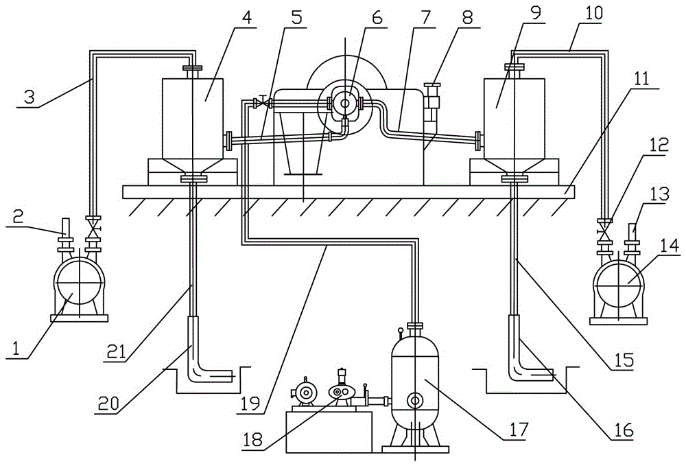
[0015] Such as figure 1 As shown, the disc filter filtrate vapor-water separation device of the present invention of the present invention is characterized in that it includes an adsorption system connected to the filter 6, a dehydration system, an air blowing and unloading system, and an electronic control system. The electronic control system also It is connected to the adsorption system, dehydration system, and air blowing and unloading system. The adsorption system includes an adsorption drainage tank 4, an adsorption vacuum tube 3 connected to the top of the adsorption drainage tank 4 at one end, and the adsorption vacuum tube 3 The other end of the adsorption vacuum pump 1 is connected to the adsorption vacuum pump 1, the adsorption vacuum exhaust pipe 2 connected to the adsorption vacuum pump 1, and the adsorption discharge pipe 21 connected to the b...


PUM


Abstract

The invention relates to a disc type filtrate steam and water separation device of a filter. The disc type filtrate steam and water separation device comprises an adsorption system, a dehydrating system, an air blowing unloading system and an electric control system; the adsorption system comprises an adsorption liquid discharging tank, an adsorption vacuum pipe, an adsorption vacuum pump, an adsorption vacuum venting pipe, an adsorption liquid discharging pipe and an adsorption flap valve; the adsorption liquid discharging tank is connected with the filter, the dehydrating system comprises a dehydrating liquid discharging tank, a dehydrating vacuum pipe, a dehydrating vacuum pump, a dehydrating vacuum venting pipe, a dehydrating liquid discharging pipe and a dehydrating flap valve; the dehydrating liquid discharging tank is connected with the filter, the air blowing unloading system comprises an air blowing pipe, a gas storage tank and a blower. The air blowing pipe is provided with an air volume control valve, and a blow-down valve is arranged at the bottom of the gas storage tank. Dehydrating and absorption in a filtering process are independently finished, and the difficult problem that the size of a filtrate tank depends on the area of the filter in a traditional process is solved, so that the process configuration is more reasonable, the plant constructing cost is lower, water and electricity cost as well as consumption of devices and spare parts are reduced.

Description

Technical field [0001] The invention belongs to the technical field of mineral processing equipment, and particularly relates to a disc filter filtrate vapor-water separation device. Background technique [0002] The traditional filter auxiliary system completes the collection and delivery of the filter filtrate by means of a filtrate cylinder, a steam-water separator and a filtrate water pump. The filtrate cylinder is a closed metal container with partitions inside to promote the separation of air and filtrate; its side wall is connected with the filter by pipes, and the upper and lower ends are respectively connected with a steam-water separator and a filtrate pump. The upper part of the filtrate tank is equipped with a safety valve to prevent excessive water accumulation in the filtrate tank, causing water to enter the vacuum pump. The size of the filtrate tank depends on the area of ​​the filter used. Corresponding to different filtration areas, there must be a filtrate tan...

Claims


Application Information

Patent Timeline
Patent Type & Authority Patents(China)
IPC IPC(8): B01D33/80
Inventor 戴兴宇蔡志浩孙德娣赵磊王瑜程杰
Owner 鞍钢集团矿业设计研究院有限公司
Why Eureka
Try Eureka