Device and method for improving yarn joint wear resistance

A wear-resistance and yarn technology, applied in the field of devices for improving the wear-resistance of yarn piecings, can solve problems such as the inability to guarantee the splicing effect of piecing, the unsuitable color spinning production process, and the failure to consider subsequent dyeing, etc. Simple operation, avoid warp stop or weft stop, ensure the effect of wear resistance and yarn body wear resistance

Active Publication Date: 2019-04-23
XINJIANG YIDA TEXTILE +3
View PDF11 Cites 0 Cited by
  • Summary
  • Abstract
  • Description
  • Claims
  • Application Information

AI Technical Summary

Problems solved by technology

[0004] The prior art uses the addition of nano-suspensions to increase the friction coefficient between fibers at the joints of the yarns to increase the bonding strength, but this invention does not consider whether the nano-suspensions attached to the joints of the yarns will affect the subsequent dyeing, etc. Process, the dyeing process has high temperature and chemical reaction, without heat treatment to make it cross-linked, it cannot guarantee that the joint gluing effect will still exist after the dyeing process is completed, it is only suitable for direct weaving of white embryo yarn, not suitable for color spinning production process Suitable for

Method used


Image

  • Device and method for improving yarn joint wear resistance
  • Device and method for improving yarn joint wear resistance

Examples


Embodiment 1

[0031] Embodiment 1 provides a device for improving the wear resistance of yarn joints.

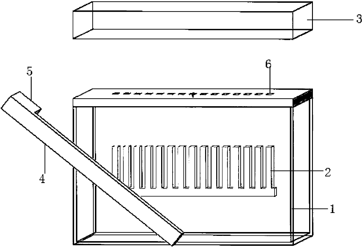
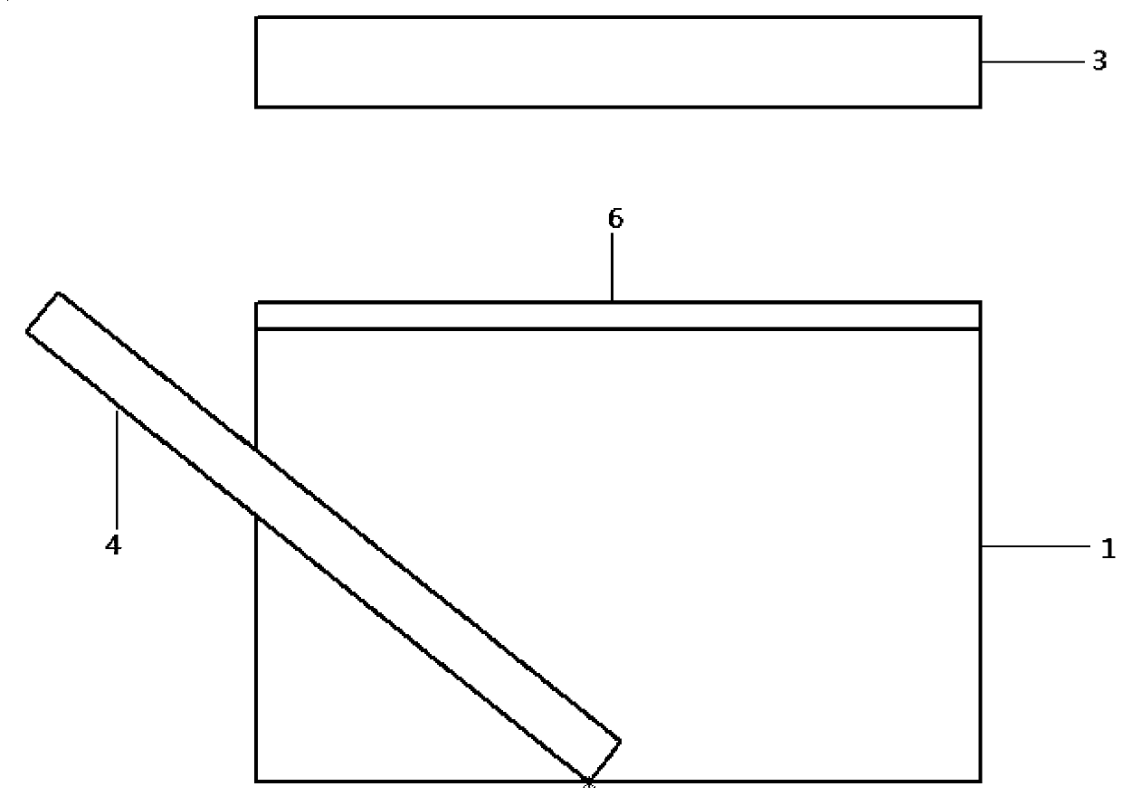
[0032] A device for improving the wear resistance of yarn joints, see figure 1 and figure 2 As shown, it includes a liquid storage tank 1, a movable needle plate 2, a heating component, a yarn clamping arm 4, a detection component, a first driving component that drives the movable needle plate 2 to move, a second driving component that drives the heating plate 3 to move, and The third driving part that drives the yarn clamping arm 4 to move, the detection component is a joint detector 5 or a photoelectric induction device, the joint detector 5 is connected to the end of the yarn clamping arm 4, and the liquid storage tank 1 There are a plurality of liquid outlets 6, and the plurality of liquid outlets 6 are distributed in columns, and there are intervals between adjacent liquid outlets 6; the glue in the liquid storage tank 1 is glue, hot melt adhesive , Slurry substances, cross-linkin...

Embodiment 2

[0040] This embodiment aims to provide a method for using the device for improving the wear resistance of yarn joints.

[0041] The device for improving the wear resistance of yarn joints is placed at the single spindle position of the winding machine. After the yarn joints are automatically knotted, the winding machine stops, and the yarn clamping arm 4 in the device for improving the wear resistance of yarn joints The joint detector 5 or the photoelectric sensor device connected to the end of the yarn clamping arm 4 confirms the position of the yarn joint, and pulls the yarn joint to the liquid outlet 6 above the liquid storage tank 1, and the movable needle plate 2 will be stained with The pin teeth of the glue are ejected to the upper surface of the liquid storage tank 1, and through the cooperation of the intermittent pin teeth and the liquid outlet 6, the glue is intermittently stuck to the joint of the yarn. After the feeding action is completed, the movable needle plate...

Embodiment 3

[0046] This embodiment aims to provide a method for using the device for improving the wear resistance of yarn joints.

[0047] The device for improving the wear resistance of yarn joints is placed at the single spindle position of the winding machine. After the yarn joints are automatically knotted, the winding machine stops, and the yarn clamping arm 4 in the device for improving the wear resistance of yarn joints The joint detector 5 or the photoelectric sensor device connected to the end of the yarn clamping arm 4 confirms the position of the yarn joint, and pulls the yarn joint to the liquid outlet 6 above the liquid storage tank 1, and the movable needle plate 2 will be stained with The pin teeth of the glue are ejected to the upper surface of the liquid storage tank 1, and through the cooperation of the intermittent pin teeth and the liquid outlet 6, the glue is intermittently stuck to the joint of the yarn. After the feeding action is completed, the movable needle plate...


PUM


Abstract

The invention discloses a device and method for improving abrasion resistance of a yarn connector. The device for improving abrasion resistance of the yarn connector comprises a liquid storage tank, a movable faller, a heating component, a yarn clamping arm, a detecting component, a first drive component driving the movable faller to move, a second drive component driving the heating plate to move and a third drive component driving the yarn clamping arm to move. The liquid storage tank is provided with a plurality of liquid outlets which are distributed in line. Intervals are formed between the adjacent liquid outlets. The movable faller is located in the liquid storage tank and provided with a plurality of needle teeth. The needle teeth are sequentially arranged, intervals are formed between the adjacent needle teeth, and the movable faller is in a comb shape. The size of the sections of the needle teeth is smaller than that of the liquid outlets. The needle teeth of the movable faller are embedded in the liquid outlets in a matched manner. According to the device and method for improving abrasion resistance of the yarn connector, disengaging is not likely to happen at the yarn connector, and the bonding effect is good.

Description

technical field [0001] The invention relates to the field of textiles, in particular to a device and method for improving the wear resistance of yarn joints. Background technique [0002] The winding process is essential in the spinning process. The winding machine can remove the defects on the yarn and then re-splicing, and can turn the bobbin into a large-capacity bobbin through splicing, which can improve the efficiency of subsequent processing. Productivity; [0003] The wear resistance of the yarn joint is weaker than that of the main body of the yarn, because the two yarns are not completely entangled after untwisting and retwisting, especially the fibers at the end of the joint are entangled on the surface of the yarn that is jointed with it, and are not effectively held so that As a result, the end fibers are not completely involved in the yarn body, and it is easy to break when weaving. In the production and processing process of the actual loom, when the yarn wit...

Claims


Application Information

Patent Timeline
Patent Type & Authority Patents(China)
IPC IPC(8): B65H69/02B65H69/04
Inventor 颜丹丹宋均燕刘霞何小东贾文杰张玉高
Owner XINJIANG YIDA TEXTILE
Why Eureka
Try Eureka