Trolley for replacement of flip-chip current transformer of centrally installed switchgear

A current transformer and flip-chip technology, which is applied to the field of replacing trolleys for current transformers in central cabinets, can solve the problems of difficult work and labor consumption, and achieve the effects of saving labor costs, reducing operation time, and shortening replacement operation time.

Inactive Publication Date: 2015-12-09
STATE GRID CORP OF CHINA +1
View PDF6 Cites 2 Cited by
  • Summary
  • Abstract
  • Description
  • Claims
  • Application Information

AI Technical Summary

Problems solved by technology

[0007] In order to solve the problem that the existing replacement of the inverted 10kV current transformer in the middle cabinet still requires personnel to enter the switch cabinet for operation, which consumes manpower, physical strength, difficulty in work and great potential safety hazards, it provides a replacement The trolley of the inverted current transformer in the middle cabinet

Method used


Image

  • Trolley for replacement of flip-chip current transformer of centrally installed switchgear
  • Trolley for replacement of flip-chip current transformer of centrally installed switchgear
  • Trolley for replacement of flip-chip current transformer of centrally installed switchgear

Examples


specific Embodiment approach 1

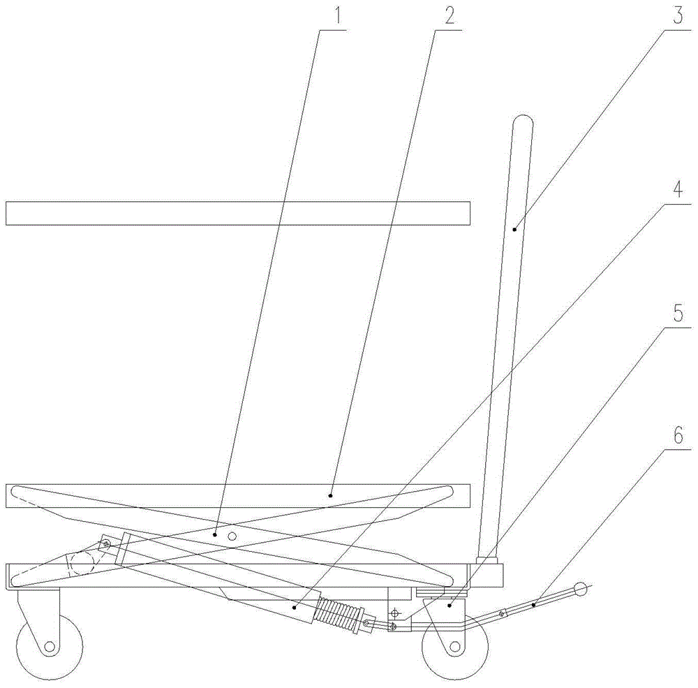
[0021] Specific implementation mode 1. Combination Figure 2 to Figure 4 Description of this embodiment, 1. The trolley for replacing the upside-down current transformer in the middle cabinet is characterized in that it includes fixing the yoke lifting device 1 between the support platform 2 and the base of the trolley, and the yoke lifting device 1 The hydraulic pump 4 fixed on the top, the lifting handle 6 connected with the hydraulic pump 4; the hydraulic pump 4 is operated by the lifting handle 6 to drive the fork arm lifting device 1, and the height of the supporting platform 2 is controlled to realize the inverted installation of the central cabinet. Replacement of current transformers.

[0022] In this embodiment, horizontal guide rails are installed on the lower surface of the support platform and the upper surface of the base. When the hydraulic pump expands and contracts, the yoke lifting device 1 is driven to move on the horizontal guide rails.

[0023] This embodi...


PUM


Abstract

The invention relates to a trolley for replacement of current transformers of centrally installed switchgears, and in particular to a trolley for replacement of a flip-chip current transformer of a centrally installed switchgear. The problems that in the prior art, people still have to enter a switch cabinet to replace flip-chip 10 kV current transformers, manpower and labor are wasted, working difficulty is high, and large potential safety hazards exist. The trolley comprises a fork arm lifting device fixed between a supporting platform and a base of the trolley, a hydraulic pump fixed on the fork arm lifting device, and a lifting handle connected with the hydraulic pump. The hydraulic pump is controlled through the lifting handle to drive the fork arm lifting device, the height of the supporting platform is controlled, and then the flip-chip current transformer of the centrally installed switchgear can be replaced. The trolley has multiple beneficial effects of being easy and convenient to operate, flexible to move, small in occupied space and the like, is applicable to complex working sites with narrow space, and completely meets rules of an electric power security working regulation. The trolley is applicable to replacement of conventional 10 kV current transformers and part of 10 kV voltage transformer in centrally installed switchgears.

Description

technical field [0001] The invention relates to a trolley for replacing a current transformer in a central cabinet, which is suitable for replacing the upside-down current transformer in a central cabinet of 10kV. Background technique [0002] In recent years, as the power consumption of factories, mines and residents has increased, the original load has been unable to meet the original production and living needs, and the number of operations to replace 10kV current transformers has also increased year by year, and a considerable part of the switchgear adopts the reverse structure of current transformers. . combine figure 1 , the traditional replacement of flip-chip 10kV current transformers is complicated to operate, and there are great safety hazards, which have brought great difficulties to our maintenance work: the specific disadvantages are as follows: [0003] 1. The space behind the cabinet door of the switchgear is narrow, and it is extremely inconvenient for main...

Claims


Application Information

Patent Timeline
Patent Type & Authority Applications(China)
IPC IPC(8): B66F7/08B66F7/28
Inventor 王阔李旭李毓隋东岩张博童金川唐克刘继勇朱贵涛侯晶
Owner STATE GRID CORP OF CHINA
Why Eureka
Try Eureka