Alignment method for metal masks

A metal mask, fine metal mask technology, applied in metal material coating process, ion implantation plating, coating and other directions, can solve the problems of color mixing, poor alignment accuracy, etc.

Inactive Publication Date: 2015-12-09
AU OPTRONICS CORP
View PDF0 Cites 5 Cited by
  • Summary
  • Abstract
  • Description
  • Claims
  • Application Information

AI Technical Summary

Problems solved by technology

[0005] Aiming at the problem of color mixing between adjacent pixels caused by the poor alignment accuracy between the metal mask and the OLED substrate in the prior art, the present invention provides a novel alignment method for the metal mask used for OLED evaporation

Method used


Image

  • Alignment method for metal masks
  • Alignment method for metal masks
  • Alignment method for metal masks

Examples


specific Embodiment

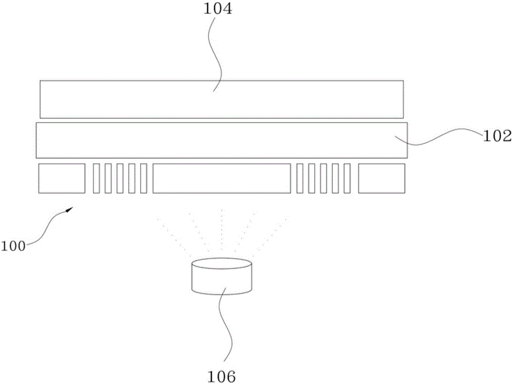
[0055] In a specific embodiment, the alignment method further includes: when the evaporation source S is evaporating different fine metal mask groups, providing a shielding layer to cover the non-evaporated area of ​​the OLED substrate. For example, when the evaporation source S evaporates the first fine metal mask group 60, a shielding layer SH1 is provided to cover the current non-evaporated area of ​​the OLED substrate; when the evaporation source S evaporates the second fine metal mask group When the group 70 performs evaporation, a shielding layer SH2 is provided on both sides of the second fine metal mask group 70 so as to cover the current non-evaporated area of ​​the OLED substrate; when the evaporation source S is applied to the third fine metal mask group 80 When performing evaporation, a shielding layer SH3 is provided to cover the current non-evaporation area of ​​the OLED substrate. Of course, the shielding layer here is not necessary, for example, in other embodi...


PUM


Abstract

The invention provides an alignment method for metal masks. According to the alignment method, a magnetic board is provided, a plurality of OLED substrates are formed above the magnetic board, and the fine metal masks are formed above the OLED substrates; each fine metal mask is at least partitioned into a first direct-row group and a second direct-row group according to the number and the size of the OLED substrates; and an evaporation source is provided to conduct evaporation on different direct-row groups in sequence so as to define sub pixel patterns of a single color. Compared with the prior art, the fine metal masks are aligned with the OLED substrates in a direct-row group manner, and evaporation is conducted on different direct-row groups of the metal masks in batches to define the sub pixel patterns of the single color; and due to the fact that the size of the direct-row groups of the metal masks is small, manufacturing is easier compared with a full mask, the alignment tolerance of the direct-row group masks and the OLED substrates can be increased, the risk of color mixing between adjacent pixels is lowered or eliminated, and the yield of products of overall substrates is increased.

Description

technical field [0001] The invention relates to a metal evaporation technology, in particular to an alignment method for a metal mask used for OLED evaporation. Background technique [0002] In recent years, organic light emitting diode (Organic Light Emitting Diode, OLED) display has been considered by the industry to be the successor to liquid crystal display ( The new display technology after LiquidCrystalDisplay (LCD), OLED display can be widely used in terminal products such as smart phones, tablet computers, and TVs. [0003] In the prior art, the evaporation of OLED is carried out in a vacuum chamber, and the OLED substrate as the processing object is installed with its evaporation surface facing down. When the metal mask for evaporation is arranged on the evaporation surface of the OLED substrate and the evaporation surface When between the sources, the evaporation source is heated to evaporate the evaporation material, and make it adhere to the surface of the OLED ...

Claims


Application Information

Patent Timeline
Patent Type & Authority Applications(China)
IPC IPC(8): C23C14/04C23C14/24
Inventor 施宏欣
Owner AU OPTRONICS CORP
Why Eureka
Try Eureka