Burner for pyrolysis and gasification and combustion method thereof

A pyrolysis gasification and burner technology, which is applied in the direction of burners, lighting and heating equipment, etc., can solve the problems of gasification efficiency reduction, low combustion efficiency, insufficient combustion, etc., and achieve high gasification efficiency and high gasification degree , the effect of simple structure

Inactive Publication Date: 2017-08-29
刘源
View PDF6 Cites 0 Cited by
  • Summary
  • Abstract
  • Description
  • Claims
  • Application Information

AI Technical Summary

Problems solved by technology

[0002] At present, in places such as hotels, guesthouses and large canteens, in order to improve cooking efficiency, a large number of liquid fuel burners are used. At the same time, among these burners, alcohol-based liquid burners have the advantages of fast heating, low use cost and environmental protection. advantages and are widely used; however, the existing alcohol-based burners generally mainly include two parts: a combustion chamber and a gasifier. Under the action of the high temperature of the gasifier, it is converted from liquid to small molecular gas, and enters the combustion chamber from the bottom of the gasifier to mix with air and burns. Since the gasifier is directly connected to the combustion chamber, when there is a large amount of fuel When injecting, the part that cannot be gasified in time will also directly enter the combustion chamber. For example, when the user needs to increase the combustion, he will often release the valve to inject more fuel. At this time, a large amount of fuel suddenly increases into the combustion chamber. Carburetor, the internal air of the gasifier is limited, the gasification efficiency is reduced, and the ungasified fuel enters the combustion chamber, resulting in low combustion efficiency and insufficient combustion, resulting in a decrease in the amount of fire within a period of time and increased fuel consumption; In view of this, the inventor has proposed a cracking gasification burner and its combustion method after repeated tests and demonstrations based on his own professional knowledge in burner-related fields for many years

Method used


Image

  • Burner for pyrolysis and gasification and combustion method thereof
  • Burner for pyrolysis and gasification and combustion method thereof
  • Burner for pyrolysis and gasification and combustion method thereof

Examples


Embodiment Construction

[0035] The present invention will be further described below in conjunction with accompanying drawing.

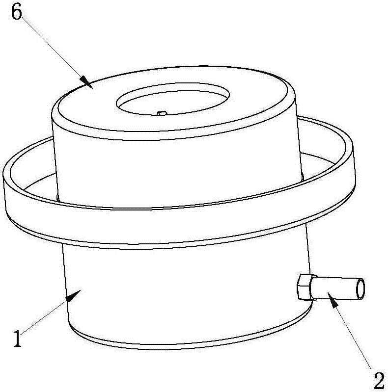
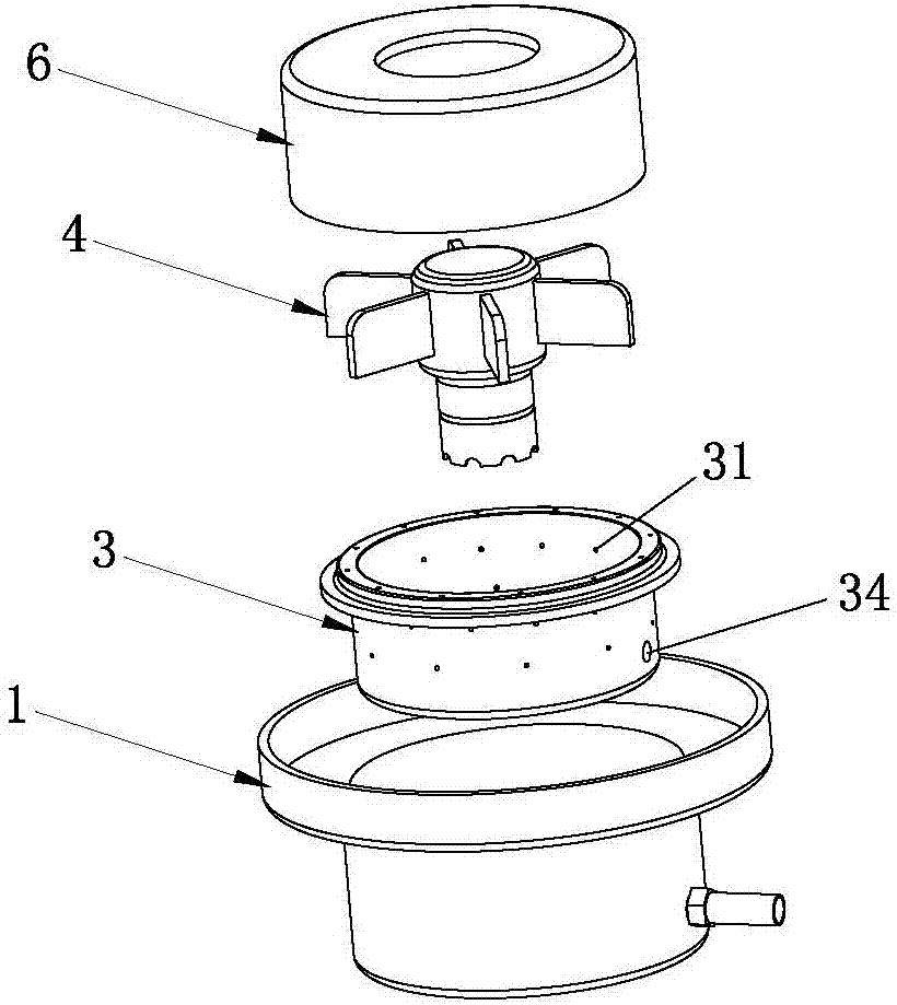
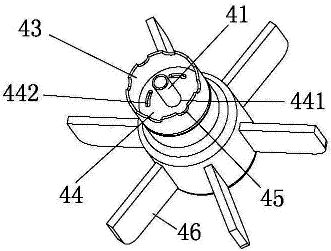
[0036] Such as Figure 1 to Figure 5 As shown, a burner for pyrolysis and gasification of the present invention includes a furnace body 1, a liquid infusion pipe 2 and a combustion chamber 3 arranged in the furnace body 1. The combustion chamber 3 is provided with several airflow holes 31, and the combustion chamber 3 The chamber 3 is connected with a gasifier 4, the inside of the gasifier 4 is provided with a conduit 41, and the top end of the conduit 41 is provided with an output hole 42, and the infusion tube 2 passes through the combustion chamber 3 and communicates with the conduit 41, The interior of the gasifier 4 is a gasification chamber 43, and the gasification chamber 43 is provided with several metal particles 5 for cracking gasification fuel. The infusion tube 2 is connected to an external storage device, and the external storage device includes a liquid stora...


PUM


Abstract

The invention relates to the technical field of combustion equipment, in particular to a combustor for splitting decomposition and gasification. The combustor comprises a furnace body, a liquid conveying pipe and a combustion chamber arranged inside the furnace body, wherein a plurality of airflow holes are formed in the combustion chamber; the combustion chamber is connected with a gasifier; a guide pipe is arranged inside the gasifier; an output hole is formed in the top end of the guide pipe; the liquid conveying pipe penetrates through the combustion chamber to be communicated with the guide pipe; a gasification chamber is arranged inside the gasifier; a plurality of metal particles for performing splitting decomposition and gasification on fuel are arranged inside the gasification chamber; during the use, fuel enters the gasifier through the liquid conveying pipe, under the high temperature action of the gasifier, one part of fuel in the gasifier is gasified, the other part of fuel forms atomized particles to be in contact with the high-temperature metal particles, the atomized particles are further subjected to splitting decomposition and gasification through the high-temperature metal particles, and finally mixed combustible gas is formed to enter the combustion chamber to be fully combusted. Obviously, the combustor has the advantages of being simple in structure, stable in combustion, and capable of saving fuel.

Description

technical field [0001] The invention relates to the technical field of combustion equipment, in particular to a cracking gasification burner and a combustion method thereof. Background technique [0002] At present, in places such as hotels, guesthouses and large canteens, in order to improve cooking efficiency, a large number of liquid fuel burners are used. At the same time, among these burners, alcohol-based liquid burners have the advantages of fast heating, low use cost and environmental protection. advantages and are widely used; however, the existing alcohol-based burners generally mainly include two parts: a combustion chamber and a gasifier. Under the action of the high temperature of the gasifier, it is converted from liquid to small molecular gas, and enters the combustion chamber from the bottom of the gasifier to mix with air and burns. Since the gasifier is directly connected to the combustion chamber, when there is a large amount of fuel When injecting, the p...

Claims


Application Information

Patent Timeline
Patent Type & Authority Patents(China)
IPC IPC(8): F23D11/22F23D11/36
Inventor 刘源
Owner 刘源
Why Eureka
Try Eureka