
A pollutant partition system based on the principle of air directional flow and its application method

A directional flow and partition system technology, applied in the field of air purification, can solve the problems of limited room airtightness, inability to guarantee the partition of polluted gas, and inconvenience of people passing through, so as to prevent heat loss, simplify commissioning and operation management, and prevent The effect of air exchange

Inactive Publication Date: 2017-12-26
TONGJI UNIV
View PDF6 Cites 0 Cited by
  • Summary
  • Abstract
  • Description
  • Claims
  • Application Information

AI Technical Summary

Problems solved by technology

[0003] In the traditional method, the method of solving the airflow exchange between the air quality control area and the external air pollution source is mainly by closing the pollution source and the pollution area, or closing the air quality control area. This method has many shortcomings and defects
For example, in the bathroom and kitchen in the family residence, the door is closed to prevent the air from the polluted area from spreading to the surroundings. However, due to the limited airtightness of the room, it will inevitably have a certain impact on the living room and bedroom. It cannot be guaranteed that the polluted gas can be completely isolated from other areas, and the closed polluted area will cause great inconvenience to the flow of people.
Laboratories are generally equipped with fume hoods, fume hoods, etc., but this is only for the removal of pollutants during some specific experimental operations

Method used


Image

  • A pollutant partition system based on the principle of air directional flow and its application method
  • A pollutant partition system based on the principle of air directional flow and its application method

Examples


Embodiment 1

[0026] Application environment: 100m 2 The family room has two bedrooms, two living rooms, one kitchen and one bathroom. The purpose of the application is to block the diffusion of harmful gases in the bathroom and kitchen to the living room and bedroom.

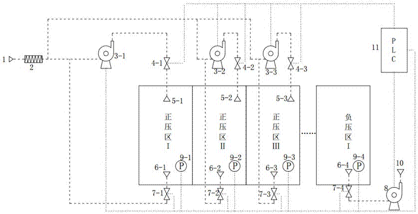
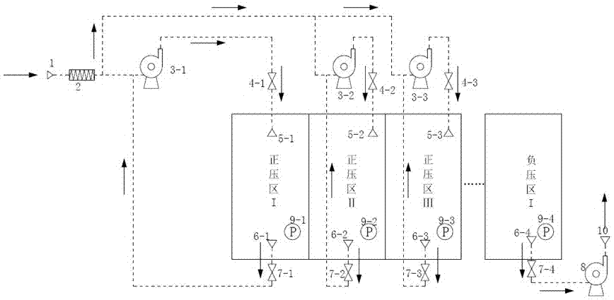
[0027] Such as figure 1 - figure 2As shown, the pollution partition system configured in this room is composed of a positive pressure air duct system, a negative pressure air duct system and an automatic control system. For the positive pressure air duct system, the general air inlet port 1 is connected to the high-efficiency filter through the air duct in turn. 2. Connect the first booster fan 3-1, the second booster fan 3-2, the third booster fan 3-3 and the first solenoid valve 4-1, the second solenoid valve 4-2, and the third solenoid valve respectively. The valve 4-3 sets the first air outlet port 5-1, the second air outlet port 5-2 and the third outlet port 5-3 respectively in the living room and the bedroom through...

Embodiment 2

[0031] Application environment: the air partition between the product warehouse of a certain factory and the adjacent production workshop, and the air partition between the warehouses corresponding to products of different quality. There are three product warehouses A, B, and C. A requires air quality and low humidity The highest, B next, and C the lowest. Area A warehouse area 100m 2 , B warehouse 150m 2 , C warehouse 120m 2 . The construction area of ​​the adjacent production workshop is 200m 2 .

[0032] The pollution partition system configured in this factory is composed of a positive pressure air duct system, a negative pressure air duct system and an automatic control system. For the positive pressure air duct system, a high-efficiency filter 2 is installed at the rear end of the main air inlet port 1, and is connected in parallel through the air ducts. Connect booster fan 3-1, the second booster fan 3-2 and the 3rd booster fan 3-3, successively as the positive pre...


PUM


Abstract

The invention relates to a pollutant obstructing system based on the air directional flowing principle and a using method of the pollutant obstructing system. The pollutant obstructing system is composed of a positive pressure air pipe system, a negative pressure air pipe system and an automatic control system. For a positive pressure area, air purified through an efficient filter is fed into the positive pressure area through a booster fan so as to ensure that the air pressure of the positive air pressure area is higher than the standard atmospheric pressure; for a negative pressure area, air is exhausted through a negative pressure draught fan via an extraction opening and discharged through an air outlet end so as to ensure that the air pressure in the negative pressure area is lower than the standard atmospheric pressure. An automatic control terminal is connected with the booster fan, electromagnetic valves, exhaust electromagnetic valves, pressure sensors and the negative pressure draught fan to complete automatic control over the positive pressure air pipe system and the negative pressure air pipe system. According to the pollutant obstructing system based on the air directional flowing principle and the using method of the pollutant obstructing system, pressure gradients are formed due to different requirements for air quality of different functional areas, it can be achieved that positive pressure in different areas is independently controlled, the debugging and operation management work is simplified, and pollutants in the area with a pollution source are effectively prevented from being conveyed to other areas.

Description

technical field [0001] The invention belongs to the technical field of air purification, and in particular relates to a pollutant isolation system based on the principle of directional air flow and a method for using the same. Background technique [0002] With the continuous development of the economy and society, people have higher and higher requirements for the air quality of the area where they live, such as the living environment, industrial production processes and special industries. However, various production and living environments of human beings are always full of various pollution sources, which affect the quality of ambient air and even endanger human health. For example, in the home environment, the kitchen is the focus of air quality control. The common pollutants in the general kitchen cooking process include benzopyrene, carbon monoxide, inhalable particulate matter, nitrogen oxides, etc. [1] , They are poorly ventilated or not ventilated in the kitchen, ...

Claims


Application Information

Patent Timeline
Patent Type & Authority Patents(China)
IPC IPC(8): F24F5/00F24F11/02F24F13/28
CPCF24F5/00F24F13/28
Inventor 徐斌龚宇吴娅
Owner TONGJI UNIV
Learn More