Real-beam scanning radar angular super-resolution method under clutter background

A scanning radar and angle super-resolution technology, which is applied in radio wave measurement systems, radio wave reflection/re-radiation, instruments, etc., can solve the problems of inability to recover multiple targets, limited super-resolution performance, and inconformity with clutter distribution characteristics, etc. question

Active Publication Date: 2015-12-09
UNIV OF ELECTRONIC SCI & TECH OF CHINA
View PDF4 Cites 16 Cited by
  • Summary
  • Abstract
  • Description
  • Claims
  • Application Information

AI Technical Summary

Problems solved by technology

[0003] Among them, the document "HuangY, ZhaY, ZhangY, etal. Real-beamscanningradarangularsuper-resolutionviasparsedeconvolution.GeoscienceandRemoteSensingSymposium(IGARSS), 2014IEEEInternational.IEEE, 2014: 3081-3084." proposes a coherent clean deconvolution method, which eliminates The way to achieve angular super-resolution, and to a certain extent solve the problem that the traditional clean algorithm cannot restore multiple targets in a single beam
However, this method has a large amount of calculation, and at the same time, the performance of the algorithm is significantly reduced when facing the extension point target.
[0004] Secondly, the literature "Guan, Jinchen, YulinHuang, JianyuYang, WenchaoLi, and JunjieWu."Improving gangular resolution based on maximum posteriori criterion for scanning radar."InRadarConference (RADAR), 2012IEEE, pp.0451-0454.IEEE, 2012." Radarangular superresolution algorithm based on Bayesian approach."InSignalProcessing(ICSP),2010IEEE10thInternationalConferenceon,pp.1894-1897.IEEE,2010."Based on the Bayesian formula, using the distribution characteristics of noise and targets to establish and solve the objective function, to achieve the restoration of the original scene in the azimuth domain , improves the azimuth angle resolution of the scanning radar to a certain extent. However, the Poisson distribution assumed by this method does not conform to the clutter distribution characteristics of the actual radar imaging. Therefore, the super-resolution performance of this method is limited

Method used


Image

  • Real-beam scanning radar angular super-resolution method under clutter background
  • Real-beam scanning radar angular super-resolution method under clutter background
  • Real-beam scanning radar angular super-resolution method under clutter background

Examples


Embodiment Construction

[0024] All steps and conclusions of the present invention are verified correctly on the Matlab2012 simulation platform, and the method of the present invention will be further elaborated below in conjunction with the accompanying drawings and specific embodiments.

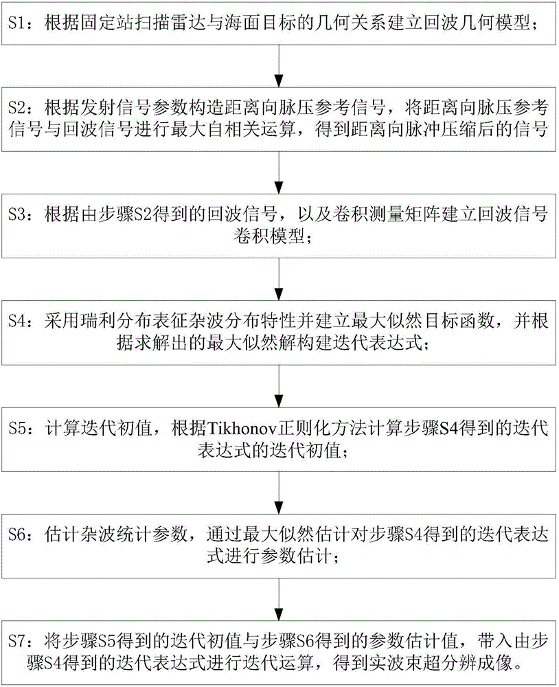
[0025] like figure 1 Shown is the flowchart of the method provided, the real beam scanning radar angle super-resolution method under the background of a kind of clutter of the present invention, comprises the following steps:

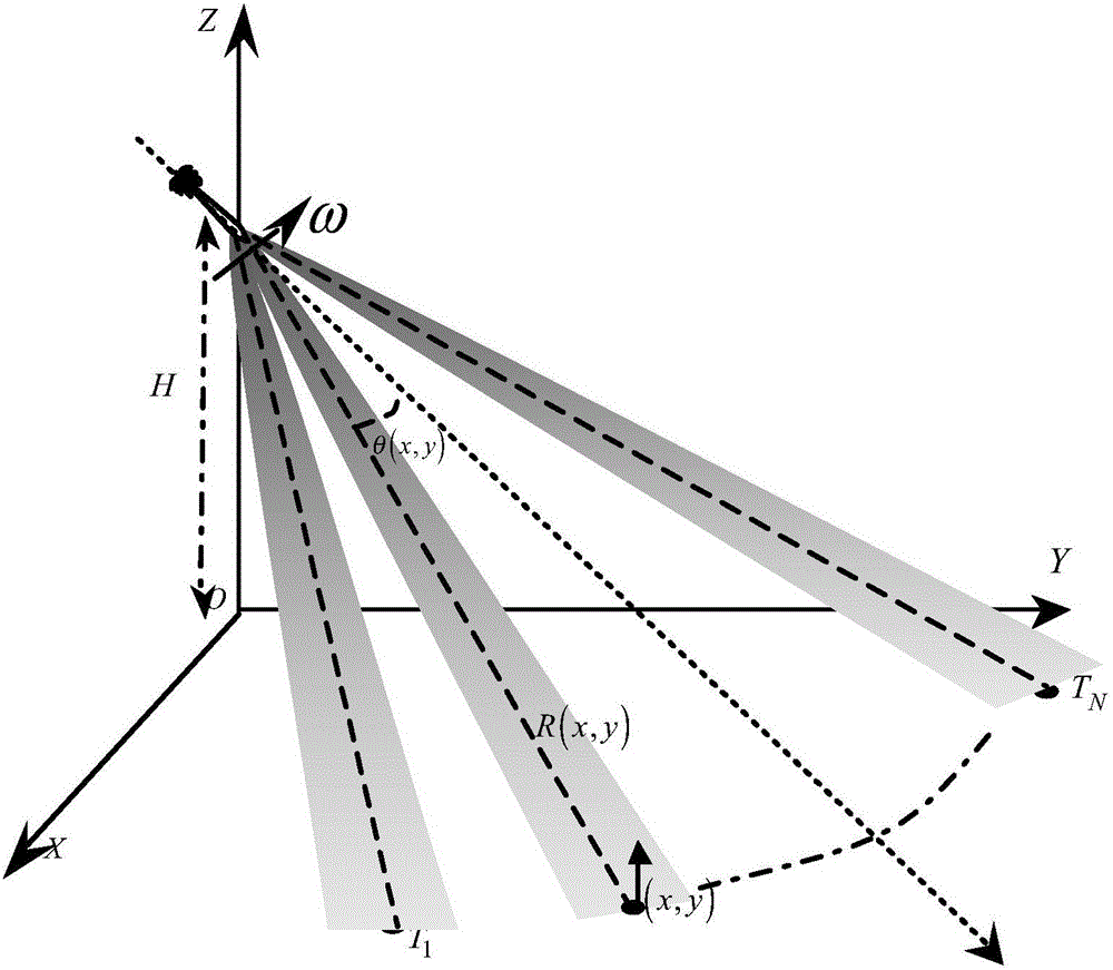
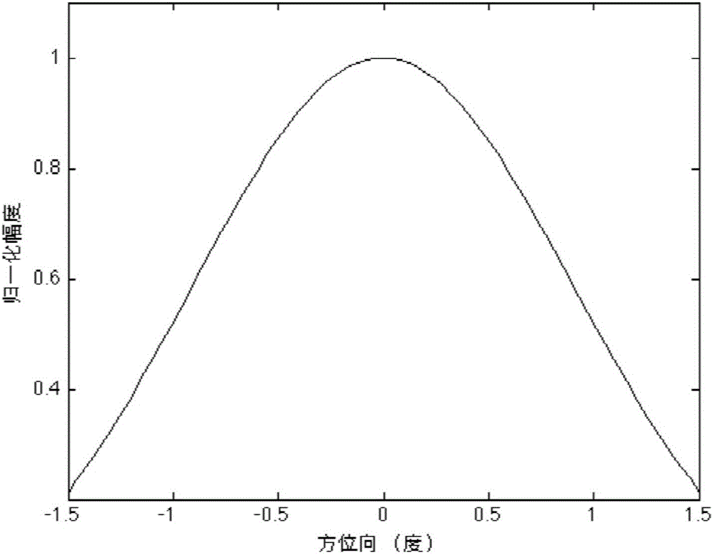
[0026] S1: Echo modeling, using fixed base station scanning imaging mode, as attached figure 2 As shown, the position of the target used in this program step is as follows image 3 As shown, the radar antenna pattern is as follows Figure 4 As shown, the scanning radar imaging parameters are shown in Table 1, and the target distribution used in the steps of this scheme is as follows Figure 5 As shown, the radar transmission signal is a linear frequency modulation signal:

[0027] ...


PUM


Abstract

The invention discloses a real-beam scanning radar angular super-resolution method under a clutter background. A convolution model of target amplitude and an antenna directional diagram is established by azimuth dimension echo through modeling according to the echo characteristic of scanning radar after pulse compression, and echo signals are processed according to a maximum likelihood deconvolution method. Clutter characteristics are represented by adopting rayleigh distribution and a target function is established, the maximum likelihood solution is obtained by solving the target function, and an iteration expression is constructed so that a problem of low azimuth dimension resolution of a conventional scanning radar imaging mode can be solved, and scanning radar angular super-resolution imaging can be realized.

Description

technical field [0001] The invention belongs to the technical field of radar imaging, and in particular relates to super-resolution imaging of sea angles by scanning radar. Background technique [0002] Radar platform sea imaging has great application value in civil and military fields such as maritime disaster search and rescue, route guidance and sea surface target recognition. In order to obtain a larger imaging range and be limited by irregular platform motion, the scanning imaging mode is usually used in the above applications to obtain two-dimensional echo images in the imaging area by sending and receiving large-bandwidth chirp signals. And for the echo signal, the two-dimensional resolution is improved through signal processing to meet the resolution requirements in practical applications. First of all, for the distance dimension, the method of matched filtering is usually used to achieve high resolution. Secondly, for the echo signal of the azimuth dimension, since...

Claims


Application Information

Patent Timeline
IPC IPC(8): G01S13/89
CPCG01S13/89
Inventor 张寅黄钰林蒲巍查月波武俊杰杨建宇
Owner UNIV OF ELECTRONIC SCI & TECH OF CHINA
Why Eureka
Try Eureka