
Isodose optimization

A technique of isodose and isodose lines used in the field of radiation therapy planning

Active Publication Date: 2015-12-09
KONINKLJIJKE PHILIPS NV
View PDF3 Cites 5 Cited by
  • Summary
  • Abstract
  • Description
  • Claims
  • Application Information

AI Technical Summary

Problems solved by technology

[0005] A new and improved method for including 3D dose information in machine parameter optimization is disclosed below, which addresses the above-mentioned problems and others

Method used


Image

  • Isodose optimization
  • Isodose optimization
  • Isodose optimization

Examples


Embodiment Construction

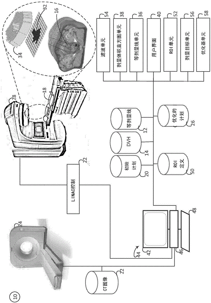
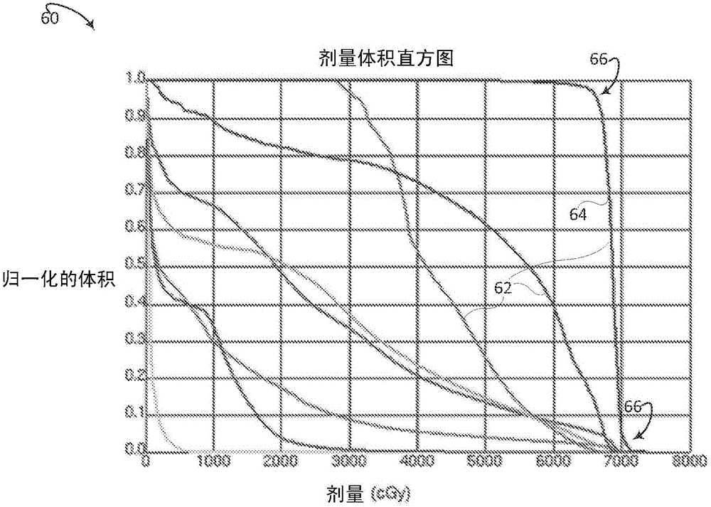
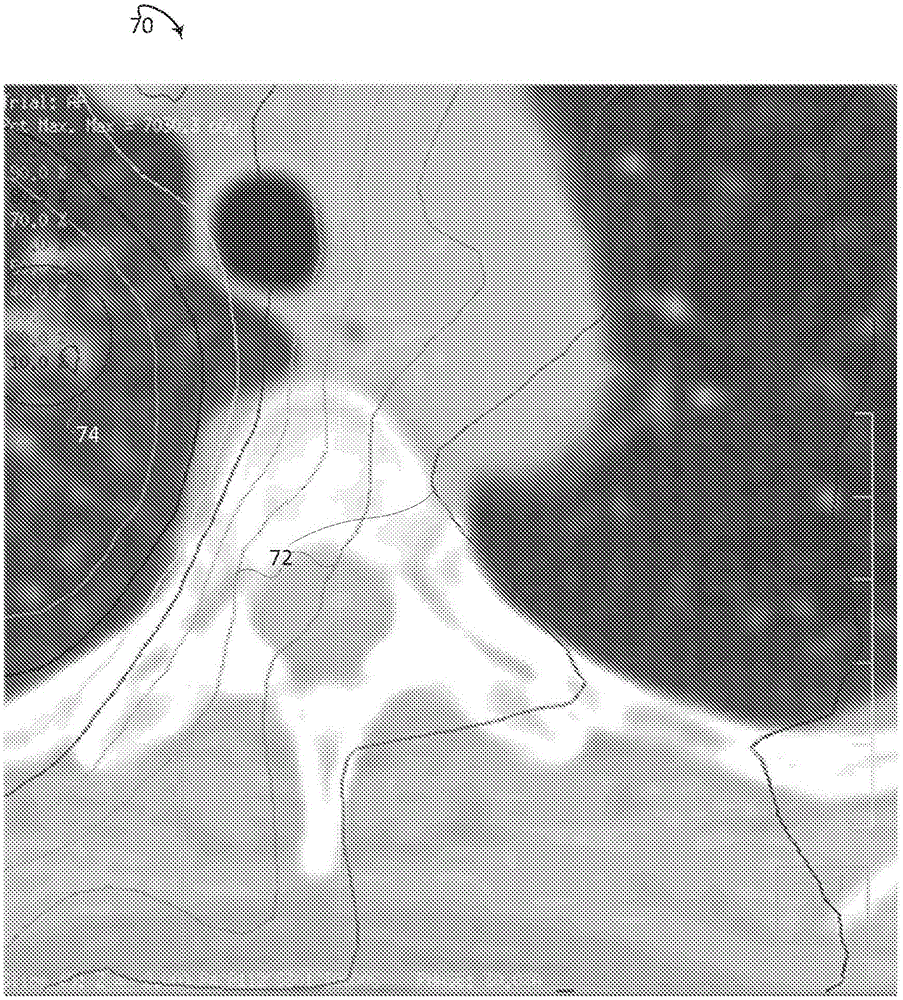
[0021] refer to figure 1 , schematically illustrates an embodiment of the isodose optimization system 10 . The system is capable of receiving planned isodose lines 12 and / or dose volume histograms (DVH) 14 for the volume 16 of the subject 18 based on an initial plan or an ideal plan 20 based on an IMRT approach, a VMAT approach, etc., Or the system can construct isodose lines 12 and / or DVH 14 from IMRT or VMAT information (eg, dose distributions created from fluence maps). The system is capable of receiving or constructing a planning image 22 (eg, a CT image from a CT imaging device 24 ) corresponding to the object volume. The optimized plan 26 includes control instructions for a radiation therapy delivery device 28 (eg, a LINAC). The radiation delivery apparatus 28 comprises control means 30 which execute control instructions according to the radiation therapy plan to deliver radiation to the target volume of the subject. The control signal controls the radiation therapy d...


PUM


Abstract

A radiation therapy planning system (10) includes an isodose line unit (36), a region of interest unit (52), and an optimization unit (58). The isodose line unit (36) receives isodose lines planned for a volume of a subject. The region of interest unit (52) defines at least one isodose region of interest based on the received isodose lines. The optimization unit (58) generates an optimized radiation therapy plan based on the at least one defined isodose region of interest and at least one dose objective for the defined region of interest.

Description

technical field [0001] The following generally relates to radiation therapy planning. The following applies in particular to use in conjunction with isodose optimization in intensity modulated radiation therapy (IMRT) or in volume modulated arc therapy (VMAT) and will be described with particular reference thereto. However, it should be understood that the following also applies to other usage scenarios, and is not necessarily limited to the aforementioned applications. Background technique [0002] The goal of radiation therapy is to deliver a lethal dose of radiation to a target region or tumor while minimizing radiation to other regions in close proximity to the organ or organ at risk (OAR). IMRT and VMAT are specific approaches to developing radiation therapy plans that deliver radiation doses with precisely delivered beams of external radiation to a target zone of a subject. IMRT is based on a point and shoot approach for one or more discrete beam angles, while VMAT i...

Claims


Application Information

Patent Timeline
IPC IPC(8): A61N5/10
CPCA61N5/1031A61N5/1047A61N2005/1074
Inventor K·A·布兹杜泽克S·弗里戈
Owner KONINKLJIJKE PHILIPS NV
Learn More