Gas flow uniform-distributing device for selective catalytic reduction (SCR) denitration

A technology of airflow uniform distribution and reduction method, which is applied in chemical instruments and methods, separation methods, and dispersed particle separation. Effect

Inactive Publication Date: 2015-12-16
CHINA NAT HEAVY MACHINERY RES INSTCO
View PDF3 Cites 1 Cited by
  • Summary
  • Abstract
  • Description
  • Claims
  • Application Information

AI Technical Summary

Problems solved by technology

[0004] Because the smoke from the kiln enters the denitrification device, due to the change of the direction of the flue, there will be obvious drift phenomenon, and some of the existing SCR mixers are not equipped with air distribution devices or only have simple devices. During the ammonia injection mixing time, it is impossible to ensure that the air flow is evenly distributed and fully mixed with the reactants, resulting in low efficiency of subsequent catalytic reactions

Method used


Image

  • Gas flow uniform-distributing device for selective catalytic reduction (SCR) denitration
  • Gas flow uniform-distributing device for selective catalytic reduction (SCR) denitration
  • Gas flow uniform-distributing device for selective catalytic reduction (SCR) denitration

Examples


Embodiment Construction

[0014] The present invention is described in detail in conjunction with the accompanying drawings.

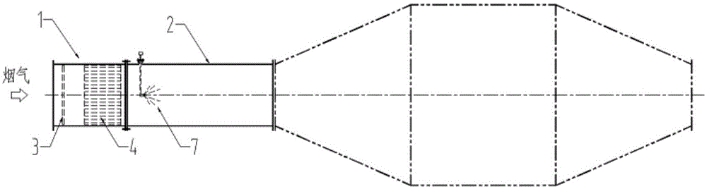
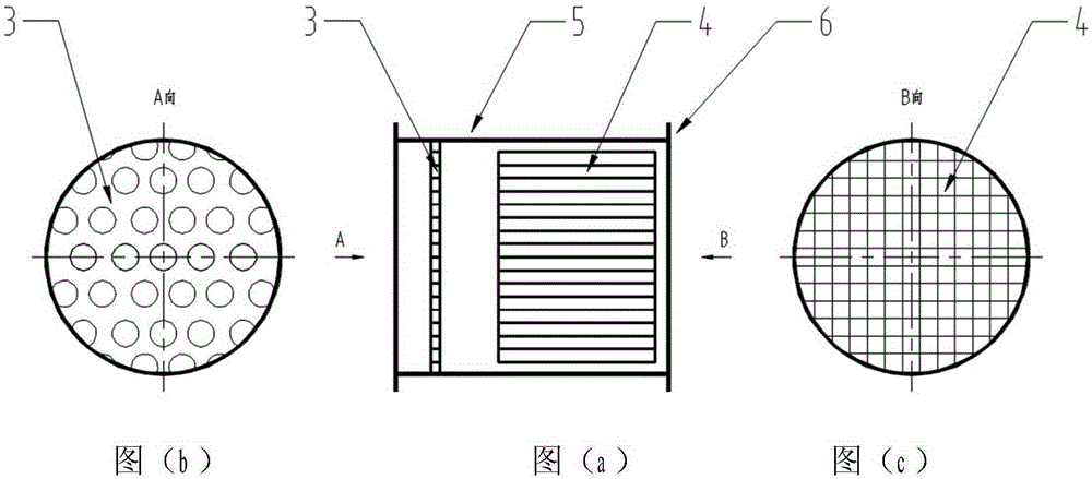
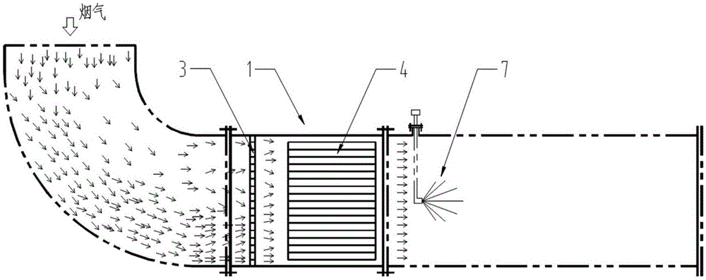
[0015] refer to figure 1 , a selective catalytic reduction (SCR) denitrification airflow uniform distribution device, including a mixer (2) in the SCR denitration device, and the airflow uniform distribution device 1 is connected to the front part of the mixer 2 in the SCR denitration device; refer to figure 2 , the air flow uniform distribution device 1 includes a casing 5, flanges 6 are provided at both ends of the casing 5, and the flanges 6 at both ends are respectively connected to the front flue and the mixer 2 in the rear SCR denitrification device through bolts, nuts and gaskets. Assembled and connected with sheets, etc., the interior of the shell 5 is fixed with the front-stage porous uniform distribution plate 3 and the rear-stage multi-tube uniform distribution device 4 along the axial direction. The pre-stage porous uniform plate 3 is a steel plate with a pluralit...


PUM


Abstract

The invention relates to a gas flow uniform-distributing device for selective catalytic reduction (SCR) denitration. The gas flow uniformly-distributing device comprises a mixer in an SCR denitration device, is connected to the front part of the mixer in the SCR denitration device, and comprises a shell, wherein flanges are arranged at the two ends of the shell; the flanges at the two ends are respectively connected with a flue at the front part and the mixer in the SCR denitration device at the rear part; a front-stage porous uniform-distributing plate and a rear-stage multitube uniform distributor are fixed inside the shell along the axial direction; the front-stage porous uniform-distributing plate is a steel plate, in which a plurality of circular holes or square holes are formed; and the rear-stage multitube uniform distributor is a tubular passage which is formed through arranging and combining a plurality of steel tubes. Biased gas flow introduced from the flue at the front part firstly passes through the front-stage porous uniform-distributing plate; the flow velocity of gas flow of the cross section is uniformly distributed; after the gas flow passes through the rear-stage multitube uniform distributor, the direction of vector of the flow direction is adjusted to be parallel to the geometric axial direction of the mixer; and flue gas is fully and efficiently mixed with a reactant sprayed from a spray nozzle arranged in the mixer in the SCR denitration device, and thus the efficiency of subsequent catalytic reaction is increased.

Description

technical field [0001] The invention belongs to the technical field of environmental engineering SCR method denitrification, and in particular relates to a selective catalytic reduction (SCR) denitrification gas flow uniform distribution device. Background technique [0002] Metallurgy, electric power and other industrial furnaces produce a large amount of industrial flue gas during production and operation, which contains a large amount of nitrogen oxide (NOx) gas. At present, the main methods for removing NOx in industry include low-nitrogen combustion, non-selective catalytic reduction (SNCR) and selective catalytic reduction (SCR). Among them, the SCR method has high denitrification reaction efficiency (above 90%) and stable operation, and is the most commonly used denitrification process. The basic principle of SCR denitrification is: using a reducing agent such as ammonia or urea to selectively reduce NOx (NO, NO2) in the exhaust gas through the action of a catalyst a...

Claims


Application Information

Patent Timeline
Patent Type & Authority Applications(China)
IPC IPC(8): B01D53/90B01D53/56
Inventor 艾华张磊边靖崔明元
Owner CHINA NAT HEAVY MACHINERY RES INSTCO
Why Eureka
Try Eureka