A combination core of pressurized multi-channel pipe splitting mold

A multi-channel pipe and split die technology, applied in the field of pressurized multi-channel pipe split die combined core field, can solve the problems of insufficient extrusion filling, fluctuating pipe wall thickness, easy breakage of core needles, etc. The effect of pressure, improving molding quality, and improving pressure bearing capacity

Inactive Publication Date: 2017-09-29
JIANGSU UNIV
View PDF2 Cites 0 Cited by
  • Summary
  • Abstract
  • Description
  • Claims
  • Application Information

AI Technical Summary

Problems solved by technology

[0006] Aiming at the deficiencies in the prior art, such as insufficient extrusion filling, dead holes, fractures, and inverted ribs, the present invention provides a pressurized multi-channel pipe splitter mold core, which avoids the need for micro-aperture multi-channel pipes During the extrusion molding process, the core needle is easy to break and deform, resulting in pipe wall thickness fluctuations and dead holes, which improves the extrusion force during work, enhances the filling efficiency and filling capacity during extrusion molding, and further improves product molding quality

Method used


Image

  • A combination core of pressurized multi-channel pipe splitting mold
  • A combination core of pressurized multi-channel pipe splitting mold
  • A combination core of pressurized multi-channel pipe splitting mold

Examples


Embodiment 1

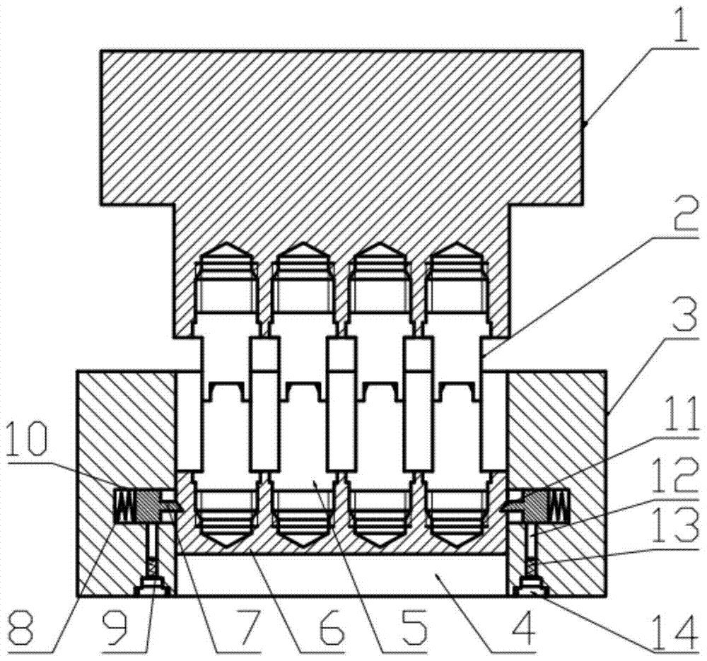
[0031] Such as figure 1 and Figure 5 As shown, a combined mold core of a pressurized multi-channel pipe splitting mold includes a mold core 1, a lower mold 3 and a lower mold support plate 6; the mold core 1 is located at the upper part, and the lower mold 3 is located at the lower part, forming The periphery of combined mold core; The center of described lower mold 3 has the lower mold through hole 4 of cuboid; The shape and size of mold through hole 4 are identical, so that the outer wall of lower mold support plate 6 can be close to the inner wall of lower mold 3; the thickness of described lower mold support plate 6 is less than the thickness of lower mold 3, so that lower mold support plate 6 can Placed in the lower die through hole 4 of the lower die 3.

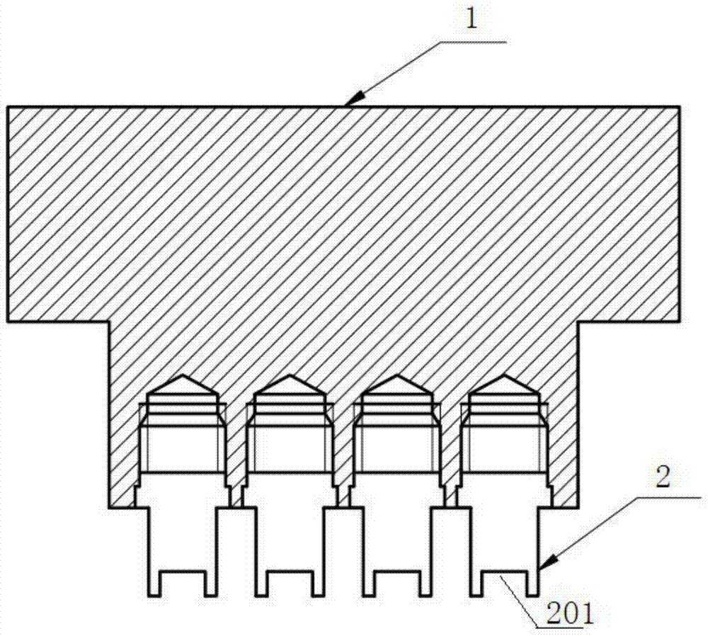
[0032] Such as image 3 As shown, the bottom of the core 1 is equipped with a plurality of equidistantly arranged upper core pins 2; the upper core pins 2 and the core 1 are threaded, and the upper core pins 2 conta...

Embodiment 2

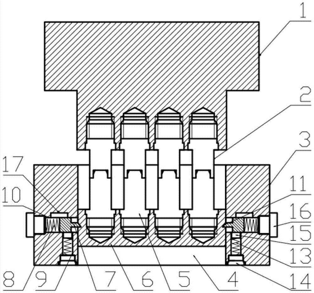
[0038] Such as figure 2 As shown, the inner wall of the lower mold 3 is symmetrically provided with two transverse sliding grooves 10, the lower mold support plate 6 is a cuboid plate; the base 702 is a cuboid base; the sliding groove 10 is a front section cuboid , the through groove of the terminal threaded hole; the bolt 16 is arranged in the threaded hole; the end of the spring 8 is against the bolt 16; the bottom of the sliding groove 10 is provided with a connected square hole 9, and the bottom of the square hole 9 is provided with a threaded hole A stop bolt 14 is arranged in the threaded hole, and the stop spring 13 is connected to the top of the stop bolt 14, and the top of the stop spring 13 is against the ejector block 15; the top of the sliding groove 10 has a slider card Groove 17; the horizontal dimension of the slider locking groove 17 is greater than the horizontal dimension of the base 702 of the boss slider 7, such as Figure 7 As shown, the horizontal dista...


PUM


Abstract

The invention belongs to the field of micro-aperture multi-channel pipe material preparation, and provides a pressurized multi-channel pipe material splitting mold combined mold core, including a mold core, a lower mold and a lower mold support plate; the center of the lower mold is provided with a lower mold through hole The outer contour of the lower mold support plate is the same as the shape and size of the lower mold through hole, the thickness is smaller than the thickness of the lower mold, and it is located inside the lower mold through hole; the bottom of the mold core is equipped with a plurality of upper mold core needles, and the lower mold support plate The top is equipped with a plurality of lower mold core needles that cooperate with the upper mold core needle; the inner wall of the lower mold is symmetrically opened with two horizontal sliding grooves; the spring and the boss slider connected with the spring are fixed horizontally in the sliding groove; the boss The slider includes a boss and a base; a supporting groove matching the front end of the boss is opened on the supporting plate of the lower mold, and the supporting plate of the lower mold is supported inside the through hole of the lower mold through the boss; the front end of the boss shrinks into the sliding groove Can be fixed in the sliding groove. The invention improves extrusion force, mold filling efficiency and mold filling ability during extrusion molding, and further improves product molding quality.

Description

technical field [0001] The invention belongs to the field of preparation of micro-aperture multi-channel pipes, in particular to a combined mold core of a pressurized multi-channel pipe splitting mold. Background technique [0002] Microchannel tube is a new type of tube developed in recent years based on the theory of micro-scale enhanced heat transfer. It adopts micro-aperture and channel close-packed structure to achieve heat transfer. Compared with conventional scale heat exchange tubes, the heat exchange efficiency can be increased by 100%. Among them, the micro-aperture multi-channel aluminum alloy heat exchange flat tube has the advantages of light weight, high heat transfer coefficient, compact structure, environmental protection, safety and reliability, etc. It has developed rapidly in demanding occasions. [0003] Each channel of the pipe is formed by micro-fine core needles arranged in parallel, and the micro-diameter core needles are prone to elastic deformation...

Claims


Application Information

Patent Timeline
Patent Type & Authority Patents(China)
IPC IPC(8): B21C25/02
CPCB21C25/02
Inventor 王匀杨夏明杜金星赵康梅许桢英柏云任乃飞陆海建王存堂任旭东
Owner JIANGSU UNIV
Why Eureka
Try Eureka