
Automatic sizing roiling-up device

A one-to-one, fixed frame technology, applied in the direction of coiling strips, transportation and packaging, thin material processing, etc., can solve the problems of on-site management and production inconvenience, low production efficiency, and occupying workshop space, so as to broaden the scope of use, Improve mobility and save time in production

Inactive Publication Date: 2015-12-16
PHIFER INC
View PDF6 Cites 2 Cited by
  • Summary
  • Abstract
  • Description
  • Claims
  • Application Information

AI Technical Summary

Problems solved by technology

[0005] These two methods of cloth drop need to be equipped with a large number of temporary transfer equipment: fabric carts or A-shaped carts. These temporary temporary storage equipment not only occupy the company's funds, but also occupy limited workshop space, which brings inconvenience to on-site management and production.
For some products with stable and good processing quality, when using swing arm folding or A-shaped car coiling type, it needs to be inspected and coiled again before they can be sold in the market, which consumes manpower, material and financial resources, and the production efficiency is low.
And when using the swing arm folding type or the A-shaped car to take up the cloth, it cannot meet the requirements of some customers who need to continue for hundreds of meters or even thousands of meters without any broken pieces. This is not only limited by the cloth car or A-shaped car, but also by the Limited to subsequent inspection vehicles

Method used

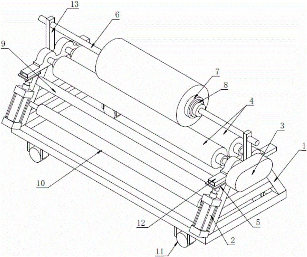
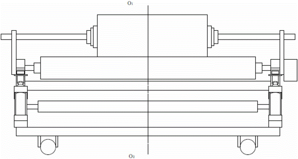

Image

  • Automatic sizing roiling-up device
  • Automatic sizing roiling-up device

Examples


Embodiment 1

[0025] Such as figure 1 and 2 As shown, a stereotyped self-rolling device includes a bracket 1, a pair of cylinders 2, a transmission motor 3, a pair of support rollers 4, a limit rod 6, two cloth guide sticks and a pair of support rods 13, and is characterized in that : the support 1 is made up of two trapezoidal side supports and a long bar connecting the two trapezoidal side supports, the long side of the trapezoidal side support is on the bottom, and the short side is on the top, and the pair of cylinders 2 are along the center of the support 1 Line 0 1 0 2 Symmetrical, installed on both sides of the trapezoidal side bracket, and the side of the bracket on the same side as the cylinder 2 is sequentially installed with two cloth guide sticks from bottom to top, the pair of support rollers 4 and the bracket 1 The long rods are parallel and installed on the fixed frame 12 above the upper crossbeam of the two trapezoidal side brackets. One side of the fixed frame 12 extend...


PUM


Abstract

The invention relates to an automatic sizing roiling-up device, which comprises a support, a pair of air cylinders, a drive motor, a pair of support drums, a limit rod, two cloth guide rollers and a pair of support rods, wherein the support comprises two trapezoidal side surface supports and a long rod, the two trapezoidal side surface supports are connected through the long rod, the air cylinders are symmetrically arranged on the two sides of the two trapezoidal side surface supports along a center line of the support, the two cloth guide rollers are arranged on the sides of the support arranged on the same side of the air cylinders from bottom to top, the support rollers are parallel to the long rod of the support, and are arranged on a fixed frame which is arranged on upper transverse beams of the two trapezoidal side surface supports, one side of the fixed frame outwardly extends above the air cylinders, the other sides of the fixed frame are connected with the two trapezoidal side surface supports through hinges, the drive motor is arranged on the side surface of the support and is connected with the support drums, two support rods are respectively arranged in the middle of the two upper transverse beams of the two trapezoidal side surface supports, and limit rods are arranged on the upper ends of the support rods. The automatic sizing roiling-up device meets the demands of clients for large non-stop point cloth rolls, and meets the practical production requirements of time saving, easy management, easy operation and high efficiency.

Description

technical field [0001] The invention belongs to the technical field of a cloth output device after a textile sizing machine, in particular to a sizing self-rolling device. Background technique [0002] According to the traditional design and processing, there are generally two ways for the cloth output device after the textile setting machine: the swing arm folding type and the A-shaped car winding type. [0003] Swing arm folding type is that when the finished product passes through the swing arm, under the control of the swing arm, the product falls into the cloth cart in a folded shape. The length of the swing arm is determined by the size of the cloth cart, and the swing frequency is determined by the shaping machine. to control the operating speed. [0004] The A-shaped car winding type is that the finished product is wound on the roller on the top of an A-shaped frame. The roller is connected with the motor by a universal joint. The winding speed depends on the speed ...

Claims


Application Information

Patent Timeline
IPC IPC(8): B65H18/16B65H23/26B65H27/00
CPCB65H18/16B65H23/26B65H27/00
Inventor 大卫霍华德·拉夫雷迪
Owner PHIFER INC
Learn More