
Depth and state detection device and method for ultra-deep mine hoisting container

A technology for containers and mines, which is applied to lifting equipment, elevators, transportation and packaging in mines, and can solve problems such as large errors, hidden safety hazards, and inaccurate parking.

Active Publication Date: 2015-12-16
CENT SOUTH UNIV
View PDF5 Cites 12 Cited by
  • Summary
  • Abstract
  • Description
  • Claims
  • Application Information

AI Technical Summary

Problems solved by technology

Due to the certain elasticity of the long steel wire rope itself and the impact of external force on the lifting container, the depth information obtained by this indirect detection method is not very reliable. If the driver does not know the real state and depth of the hoisting container, if the reel continues to work, it is likely to cause a serious accident of broken rope
[0003] When the lifting container needs to stop in the middle section, it needs to slow down and crawl first, and send a stop signal through the mechanical or electromagnetic travel switch. At this time, due to the elasticity of the steel wire rope and other reasons, the actual stop point is not very accurate, which brings great inconvenience to personnel and material transportation. Some difficulties and safety hazards
Moreover, the underground environment is harsh, and the travel switch is damaged from time to time, which brings inconvenience to normal operation and also poses safety hazards
[0004] However, in ultra-deep mines (above 1500 meters), the influence of the elastic elongation of the wire rope cannot be ignored, the load of the lifting container is larger, and the running speed is faster. The method of relying on the indirect detection of the rotary encoder + the stop signal of the travel switch has a large error , may bring problems such as inaccurate parking, instability, etc., and bring difficulties and safety hazards to personnel and vehicles.

Method used


Image

  • Depth and state detection device and method for ultra-deep mine hoisting container
  • Depth and state detection device and method for ultra-deep mine hoisting container
  • Depth and state detection device and method for ultra-deep mine hoisting container

Examples


Embodiment Construction

[0040] The present invention will be further described below in conjunction with the accompanying drawings and embodiments.

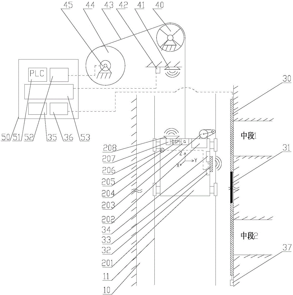
[0041] Such as figure 1 As shown, an ultra-deep mine hoist container depth and state detection device includes a multi-core cable 31, a wellhead laid on one side of the mine shaft 10 and all coded cables 30 in the middle section, a multi-core cable 31, an antenna box 33, and a carrier generator device 34, address signal detection decoder 35, three-axis accelerometer 204, DSP acquisition and calculation module 205, wireless signal transmitter 207, transmitting directional antenna 208, receiving directional antenna 41, wireless signal receiver 42 and industrial computer 53;

[0042] The multi-section coded cables 30 are connected by a multi-core cable 31;

[0043] The antenna box 33, the three-axis accelerometer 204, the DSP acquisition and calculation module 205 and the wireless signal transmitter 207 are arranged on the lifting container 201;

[0044...


PUM


Abstract

The invention discloses a depth and state detection device and method for an ultra-deep mine hoisting container. The device comprises a wellhead arranged on one side of a mine shaft, coding cables laid on all middle sections, an antenna box, an address detection decoder, a carrier generator, a triaxial accelerometer, a digital signal processor (DSP) collection and operation module, a wireless signal transmitter, a transmitting directive antenna, a receiving directive antenna, a wireless signal receiver and an industrial personal computer. The entire device is simple in structure, low in cost and convenient to operate. According to the method, the triaxial accelerometer is provided for detecting the motion state of the container in a non-critical position, integration is conducted on the accelerometer so that the speed and depth of the container can be obtained, the information can be compared with information acquired from a rotary encoder, hence, information reliability is guaranteed, and operation safety of equipment is guaranteed as well.

Description

technical field [0001] The invention relates to an ultra-deep mine hoisting container depth and state detection device and method. Background technique [0002] At present, in the field of mine hoisting, the depth detection of the hoisting container is basically to measure the rotation angle of the reel through the rotary encoder, and then convert it into the moving distance of the wire rope according to the diameter of the reel, and indirectly obtain the depth information of the hoisting container. Due to the certain elasticity of the long steel wire rope itself and the impact of external force on the lifting container, the depth information obtained by this indirect detection method is not very reliable. If the driver does not understand the true state and depth of the lifting container, the continued work of the reel is likely to cause a serious accident of broken rope. [0003] When the lifting container needs to stop in the middle section, it needs to slow down and cra...

Claims


Application Information

Patent Timeline
IPC IPC(8): B66B19/06B66B3/02B66B3/00
Inventor 谭建平薛少华刘溯奇林波吴志鹏
Owner CENT SOUTH UNIV
Learn More