Process for producing alkali

A production process and cathode chamber technology, applied in the field of alkali production process, can solve the problems of reduced electrolyte resistivity, waste, and reduced anode conductivity, so as to prevent the alkali from re-reacting, reduce the waste of electric energy, and improve the electrolysis rate. Effect

Active Publication Date: 2015-12-16
ZHEJIANG OCEANKING DEVELOPMENT CO LTD
View PDF4 Cites 11 Cited by
  • Summary
  • Abstract
  • Description
  • Claims
  • Application Information

AI Technical Summary

Problems solved by technology

[0003] However, in the process of electrolyzing saturated NaCl solution in the chlor-alkali industry, since the unreacted hydroxide ions in the cathode chamber will gradually accumulate in the cathode chamber during the electrolysis process, it is possible to reverse osmosis through the cation exchange when a certain concentration is reached. Membrane enters the anode compartment
Hydroxide ions are more likely to lose electrons than chloride ions in the case of electrolysis, and the chlorine gas produced is easy to react with hydroxide ions, and then the amount of chlorine gas produced in the anode chamber will decrease, and the sodium ions that pass through the cation exchange membrane will be reduced. The amount will be reduced accordingly, so the output of sodium hydroxide will be reduced
[0004] At the same time, the resistivity of the electrolyte will decrease with the rise of the solution temperature, so the anolyte often needs to be raised before entering the anode chamber, which will waste more energy
[0005] In addition, the chlorine gas produced is also relatively easy to dissolve in water or adhere to the surface of the anode electrode, which greatly reduces the conductivity of the anode.

Method used


Image

  • Process for producing alkali

Examples


Embodiment Construction

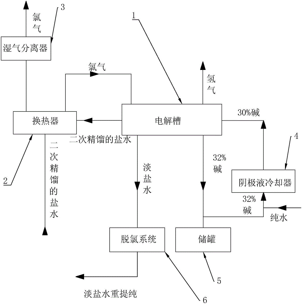
[0017] refer to figure 1 The embodiments of the present invention will be further described.

[0018] The present invention is a production process of alkali. The alkali described here mainly refers to a sodium hydroxide solution with a mass fraction of 32%. 3 The flow rate of / hr passes through the cold fluid pipeline of the heat exchanger 2, enters the anode chamber of the electrolytic cell 1 after being preheated, and the temperature reached by the preheating is 55°C. The cathode chamber is connected with a mixture of 32±0.5% alkali and pure water produced by the electrolysis of the cathode chamber. The concentration after mixing is 30±0.5%, and the flow of catholyte is controlled at 14m 3 / hr. After that, start to gradually increase the current in the solution, and when the current reaches 5KA, start to gradually add acid to the anode chamber, adjust the pH to 4 at first, and then continue to add acid to the anode chamber every other hour to make The pH value continues ...


PUM


Abstract

The invention relates to a process for producing alkali. The process comprises the following steps: a, secondary refined brine is preheated through a heat exchanger and enters an anode chamber of an electrolytic bath; when the current reaches 5KA, acid is added into the anode chamber; b, chlorine generated by electrolysis is used for preheating the secondary refined brine through the heat exchanger, so that the temperature of the secondary refined brine reaches 55 DEG C; c, part of alkali with the concentration being 32+/-0.5 percent exhausted from a cathode chamber is mixed with a moderate amount of pure water to generate alkali with the concentration being 30+/-0.5 percent, and the alkali with the concentration being 30+/-0.5 percent enters the cathode chamber and is electrolyzed in the cathode chamber to generate hydrogen; d, the temperature of the electrolytic bath in the whole electrolytic reaction process is regulated and controlled to 85-87 through a cathode liquor cooler; e, when the concentration of cathode liquor achieves 2+/-0.5 percent, the cathode liquor is exhausted from the cathode chamber; after the cathode liquor passes through the cathode liquor cooler, part of the cathode liquor is reused into the cathode chamber, and part of the cathode liquor is output to a storage tank. The process reduces energy waste, is beneficial to quickly exhausting the generated gas, increases the production rate of alkali, and improves the conductivity of liquor.

Description

technical field [0001] The invention relates to the field of chemical production, in particular to a production process of alkali. Background technique [0002] The chlor-alkali industry uses electrolysis of saturated NaCl solution to produce NaOH, Cl2 and H2, and uses them as raw materials to produce a series of chemical products. The chlor-alkali industry is one of the most basic chemical industries. Its products are not only used in the chemical industry itself, but also widely used in light industry, textile industry, metallurgical industry, petrochemical industry and public utilities. [0003] However, in the process of electrolyzing saturated NaCl solution in the chlor-alkali industry, since the unreacted hydroxide ions in the cathode chamber will gradually accumulate in the cathode chamber during the electrolysis process, it is possible to reverse osmosis through the cation exchange when a certain concentration is reached. The membrane enters the anode chamber. Hydr...

Claims


Application Information

Patent Timeline
Patent Type & Authority Applications(China)
IPC IPC(8): C25B1/34
Inventor 杜旭华周南王世周任科恩俞先康
Owner ZHEJIANG OCEANKING DEVELOPMENT CO LTD
Why Eureka
Try Eureka