
Electromagnetic valve assembly of electronic jacquard machine

A solenoid valve component and electronic jacquard technology, applied in jacquard machines, textiles, textiles and papermaking, etc., can solve problems such as short service life, non-wear resistance, and increased energy consumption, and achieve improved service life, less wear and tear, and reduced energy consumption the effect of consumption

Active Publication Date: 2015-12-16
浙江慧林智能设备有限公司
View PDF9 Cites 8 Cited by
  • Summary
  • Abstract
  • Description
  • Claims
  • Application Information

AI Technical Summary

Problems solved by technology

The material of the pulley bracket structure is generally made of plastic, so when working for a long time, the pulley moves at high speed, and the plastic of the pulley bracket is easy to age, not wear-resistant, and has a short service life under high speed, high temperature and high pressure; another electronic in the current industry The jacquard machine electromagnetic valve assembly uses the suction force of the electromagnet to overcome the pressure of the compression spring, so that the moving iron rotates, the clamping connection between the moving iron and the vertical hook falls off, and finally the pulley block and the wire thread descend; The number of times the wire descends is more, and most of the time is in the descending process, so this operation method requires a longer power supply time for the electromagnet, resulting in an increase in energy consumption

Method used


Image

  • Electromagnetic valve assembly of electronic jacquard machine
  • Electromagnetic valve assembly of electronic jacquard machine
  • Electromagnetic valve assembly of electronic jacquard machine

Examples


Embodiment 1

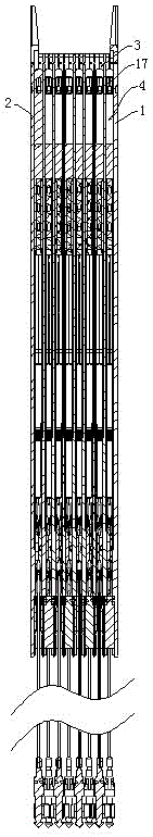
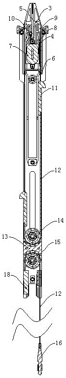
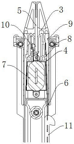
[0019] Such as figure 1 , figure 2 , image 3 , Figure 4 As shown, the electromagnetic valve assembly of the electronic jacquard machine described in this embodiment includes a base plate 1, a panel 2 and several splints 3 arranged between the base plate 1 and the panel 2, and at the top of the base plate 1, the panel 2 and the splint 3 A groove 5 for PCB board insertion is provided, an electromagnet 7 is arranged in the splint 3 below the groove 5, and the electrode 10 of the electromagnet 7 extends into the groove 5; Vertical passage 6, the width of the vertical passage 6 above the electromagnet 7 lower end faces is greater than the width of the vertical passage 6 below, and the side of the electromagnet 7 is slightly lower than the side of the vertical passage 6; A suction piece 4 is arranged inside, and the suction piece 4 slides up and down in the vertical passage 6; a boss 8 is arranged on the side wall of the vertical passage 6 above the electromagnet 7, and the bo...

Embodiment 2

[0024] Such as Figure 5 , Figure 6As shown, the electromagnetic valve assembly of the electronic jacquard machine described in this embodiment includes a base plate 1, a panel 2 and several splints 3 arranged between the base plate 1 and the panel 2, and at the top of the base plate 1, the panel 2 and the splint 3 A groove 5 for PCB board insertion is provided, an electromagnet 7 is arranged in the splint 3 below the groove 5, and the electrode 10 of the electromagnet 7 extends into the groove 5; Vertical passage 6, the width of the vertical passage 6 above the electromagnet 7 lower end faces is greater than the width of the vertical passage 6 below, and the side of the electromagnet 7 is slightly lower than the side of the vertical passage 6; A suction piece 4 is arranged inside, and the suction piece 4 slides up and down in the vertical passage 6; a boss 8 is arranged on the side wall of the vertical passage 6 above the electromagnet 7, and the boss 8 protrudes from the s...


PUM


Abstract

The invention relates to the field of textile machines, in particular to an electromagnetic valve assembly of an electronic jacquard machine. The electromagnetic valve assembly comprises a bottom plate, a panel and sandwiched plates. Vertical channels are formed in the two sides of the sandwiched plates. Attraction pieces are arranged inside the vertical channels, bosses are arranged on the portions, above electromagnets, of the side walls of the vertical channels, and the bosses and the electromagnets are located on the same side of the vertical channels. Through holes are formed in the upper ends of the attraction pieces and used for fastening the bosses. Pulley sets are arranged vertically at the lower ends of the sandwiched plates, vertical hooks are arranged at the lower ends of the attraction pieces on the two sides of the same sandwiched plate and connected through a harness cord, the harness cords are wound around upper pulleys in the pulley sets, and harness cords are wound around lower pulleys in the pulley sets. A fixed block is arranged at one end of each harness cord, the fixed blocks are fixed to the sandwiched plates, and rapid connectors are arranged at the other ends of the harness cords. According to the electromagnetic valve assembly of the electronic jacquard machine, the metal attraction pieces are adopted for sliding inside the vertical channels, abrasion is not likely to occur, and the service life is prolonged.

Description

technical field [0001] The invention relates to the field of textile machinery equipment, in particular to a solenoid valve assembly of an electronic jacquard machine. Background technique [0002] At present, the domestic electronic jacquard machine equipment manufacturing has sprung up, and a hundred schools of thought contend. However, for the high-end market with high speed, high load and large needle count, imported models are still widely used. The main reason is that the processing and assembly precision and materials of domestic Jacquard machine parts are significantly worse than those of imported models. At present, the transmission mechanism of the electromagnetic valve assembly of the electronic jacquard machine in China is generally composed of a plastic vertical hook and a moving iron metal body. The plastic vertical hook has the defects that the plastic reed is not fatigue-resistant and cannot work normally at high temperatures; The disadvantage of this kind ...

Claims


Application Information

Patent Timeline
IPC IPC(8): D03C3/20
Inventor 孙善林
Owner 浙江慧林智能设备有限公司
Learn More