
Drilling machine system based on dynamic control of tool face of self-adaptive downhole drilling tool and well drilling method

A dynamic control and tool face technology, which is applied to the automatic control system of drilling, drilling equipment and methods, drilling equipment, etc., can solve the problem of effectively controlling the tool face and wellbore trajectory of difficult drilling tools, increasing drilling costs, and reducing work efficiency and other problems, to achieve simple and fast measurement or estimation, reduce the accuracy requirements, and reduce the effect of accuracy requirements

Active Publication Date: 2015-12-16
CHINA NAT OFFSHORE OIL CORP +1
View PDF5 Cites 5 Cited by
  • Summary
  • Abstract
  • Description
  • Claims
  • Application Information

AI Technical Summary

Problems solved by technology

Obviously, this method will affect the drilling schedule, reduce work efficiency, and increase drilling costs
In addition, in the conventional sliding steerable drilling process, because the drill string of the sliding steerable drilling system does not rotate, it is easy to generate a large frictional torque
For the wellbore with clear formation conditions, the frictional torque can be overcome by rotating the turntable according to the well depth and the combination characteristics of the drilling tool; but for the flexible drill string system with large slenderness ratio, it is difficult to realize the Effective control

Method used


Image

  • Drilling machine system based on dynamic control of tool face of self-adaptive downhole drilling tool and well drilling method
  • Drilling machine system based on dynamic control of tool face of self-adaptive downhole drilling tool and well drilling method
  • Drilling machine system based on dynamic control of tool face of self-adaptive downhole drilling tool and well drilling method

Examples


Embodiment Construction

[0037] The present invention will be described in detail below in conjunction with the accompanying drawings and embodiments.

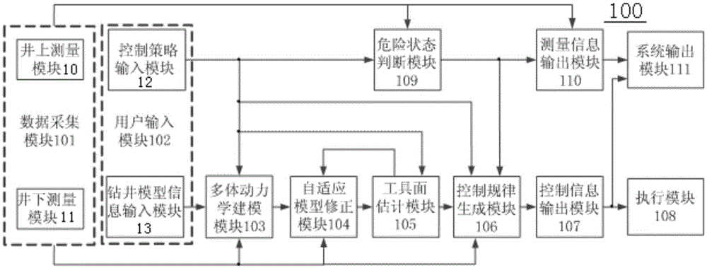
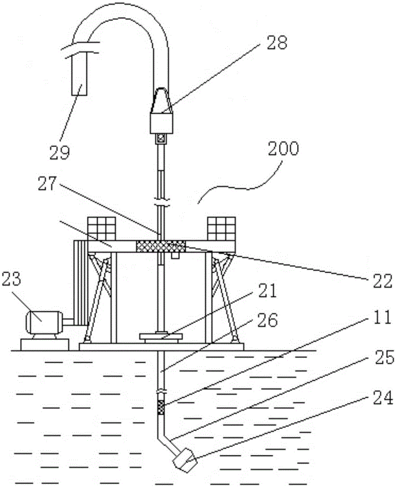
[0038] like figure 1 , figure 2 As shown, the drilling rig system of the present invention includes a dynamic control system 100 and a drilling system 200 .

[0039] like figure 1 As shown, the dynamic control system 100 includes a data acquisition module 101, a user input module 102, a multi-body dynamics modeling module 103, an adaptive model correction module 104, a tool face estimation module 105, a control law generation module 106, and a control information output module 107 , an execution module 108 , a dangerous state judging module 109 , a measurement information output module 110 and a system output module 111 .

[0040] Among them, the data collection module 101 transmits the collected working state measurement information of the drilling system to the multibody dynamics modeling module 103, the adaptive model correction module 104, the...


PUM


Abstract

The invention discloses a drilling machine system based on dynamic control of a tool face of a self-adaptive downhole drilling tool and a well drilling method. The drilling machine system comprises a dynamic control system and a well drilling system, the dynamic control system comprises a data collection system, a control strategy input module, a well drilling model information input module, a multi-body dynamics modeling module, a self-adaptive model correction module, a tool face estimation module, a control rule generation module, an execution module and a danger state judgment module. A user inputs a control strategy and a well drilling model, the data collection module collects system drilling condition, the multi-body dynamics modeling module performs multi-body dynamics modeling on the basis of the well drilling model, the self-adaptive model correction module corrects a multi-body dynamics model on the basis of the drilling condition, the tool face estimation module and the control rule generation module calculate control rules for controlling the execution module on the basis of the control strategy, the drilling condition and the multi-body dynamics model after being corrected, and the danger state judgment module gives out an alarm when the system is in a danger state. The drilling machine system can remarkably improve well drilling efficiency and accuracy and can be widely used for downhole directional drilling.

Description

technical field [0001] The invention relates to an oil and gas field drilling rig system and a drilling method, in particular to a rotary table drilling rig system and a drilling method based on multi-body dynamics model-based adaptive downhole drilling tool face dynamic control. Background technique [0002] Sliding drilling using angled drilling tools is a commonly used drilling method in petroleum directional drilling. Due to changes in formation lithology, changes in mud pump speed, wear of drill bits and power drilling tools, etc., the tool face of downhole drilling tools is prone to drift, which will cause the wellbore trajectory to deviate from the designed trajectory. When the ground engineer finds that the tool face of the drilling tool drifts, the conventional treatment method is to immediately stop the drilling and lift the drilling tool, adjust the tool face of the drilling tool to the required position, and then go down and continue drilling. Obviously, this me...

Claims


Application Information

Patent Timeline
Patent Type & Authority Applications(China)
IPC IPC(8): E21B3/04E21B44/00
Inventor 程载斌曹砚锋姜伟周建良刘书杰李汉兴武广瑷李峰飞
Owner CHINA NAT OFFSHORE OIL CORP
Learn More