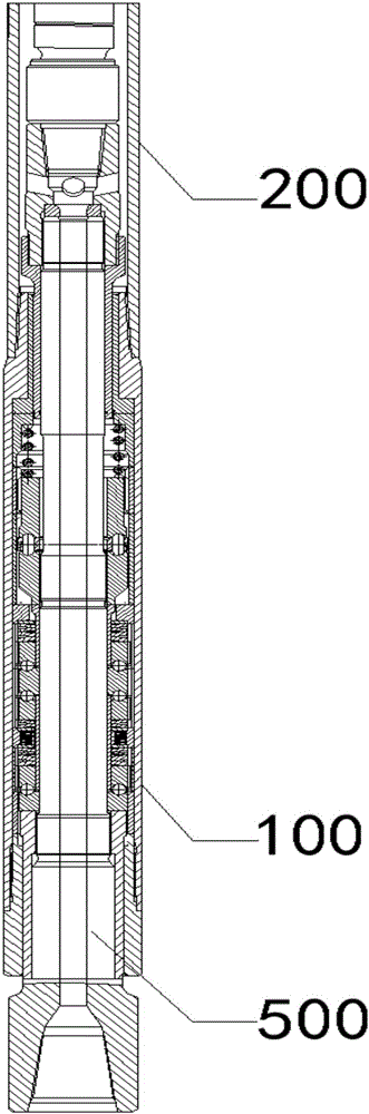
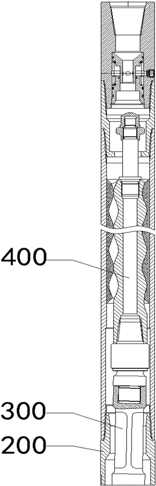
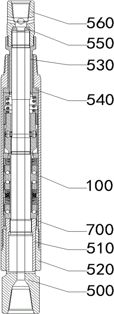
Screw drill

A screw drilling tool and threaded connection technology, which is used in drilling equipment, earth-moving drilling, driving devices for drilling in wellbore, etc. and other problems, to achieve the effect of improving the drilling speed and drilling quality, extending the WOB action distance, and improving the difficult control of the WOB.

Active Publication Date: 2015-12-16
四川泰和石油科技有限公司
View PDF7 Cites 8 Cited by
  • Summary
  • Abstract
  • Description
  • Claims
  • Application Information

AI Technical Summary

Problems solved by technology

[0003] In the current drilling process, the main way to control the drilling of the drill bit to the bottom of the well is to manually control the intermittent drilling, and the axial direction of various drilling tools in the drill string, including the screw drilling tool, is rigid. The drill bit is always in the intermittent drilling mode during the actual drilling process, and the continuous drilling distance of the drill bit is very short after each drill delivery, and the high-frequency drill delivery also brings continuous impact damage to the drill bit, although The screw drilling tool improves the drilling speed by increasing the drill bit speed, but it increases the impact force on the drill bit when sending the drill, and thus increases the fluctuation range of the output power performance of the screw drill tool, which shortens the working life of the drill bit. Reduced work efficiency
[0004] Therefore present screw drilling tools generally have the following defects: there is no pressure-on-bit extension function, which cannot solve the problem that the continuous drilling depth of the drill bit is shallow, and the working efficiency of the drill tool and the drill bit is low; Continuous impact between layers, short life of drill bits and drilling tools; unreasonable structure of drive shaft assembly

Method used


Image

  • Screw drill
  • Screw drill
  • Screw drill

Examples


Embodiment Construction

[0040] In order to make the purpose, technical solutions and advantages of the embodiments of the present invention clearer, the technical solutions in the embodiments of the present invention will be clearly and completely described below in conjunction with the drawings in the embodiments of the present invention. Obviously, the described embodiments It is a part of embodiments of the present invention, but not all embodiments. The components of the embodiments of the invention generally described and illustrated in the figures herein may be arranged and designed in a variety of different configurations. Accordingly, the following detailed description of the embodiments of the invention provided in the accompanying drawings is not intended to limit the scope of the claimed invention, but merely represents selected embodiments of the invention. Based on the embodiments of the present invention, all other embodiments obtained by persons of ordinary skill in the art without cre...


PUM


Abstract

The invention provides a screw drill belonging to the field of drilling tools. The screw drill comprises a motor assembly, an upper shell and a lower shell, wherein the upper shell and the lower shell form a transmission chamber; the transmission chamber is internally provided with a transmission shaft and a strainer; through holes allowing drilling fluid to flow are formed in the transmission shaft; the bottom of the strainer is fixedly connected with an upper dynamic sliding bearing; the top of the inner wall of the lower shell is provided with an upper static sliding bearing; the bottom of the outer wall of the transmission shaft is sleeved by a lower dynamic sliding bearing; the bottom of the inner wall of the lower shell is in threaded connection with a lower static sliding bearing; a buffering disc spring group composed of a plurality of disc springs is arranged between the lower dynamic sliding bearing and the upper dynamic sliding bearing; and the transmission shaft is sleeved by the buffering disc spring group. By using the screw drill, the effective working time of a bit can be effectively prolonged, the drilling efficiency of the bit can be effectively increased, the bit pressure acting distance can be effectively increased, and the effective drilling depth of the bit at the one-time bit feeding pressure is can be increased.

Description

technical field [0001] The present invention relates to the field of drilling tools, in particular to screw drilling tools. Background technique [0002] The currently commonly used screw drilling tool is a downhole power drilling tool driven by the hydraulic energy of the drilling fluid. It has the function of increasing the rotation speed of the drill bit and thus improving the drilling efficiency. It also has the function of drilling directional, horizontal and other deviated sections The function, and its manufacturing and use cost is low, safety and reliability are high, and it has been widely used for many years. [0003] In the current drilling process, the main way to control the drilling of the drill bit to the bottom of the well is to manually control the intermittent drilling, and the axial direction of various drilling tools in the drill string, including the screw drilling tool, is rigid. The drill bit is always in the intermittent drilling mode during the actu...

Claims


Application Information

Patent Timeline
Patent Type & Authority Applications(China)
IPC IPC(8): E21B4/02
Inventor 李少江
Owner 四川泰和石油科技有限公司
Why Eureka
Try Eureka