Skid-mounted water injection well circulating well washing device and circulating well washing technique
A technology for water injection and well cleaning, which is applied in the directions of flushing wellbore, wellbore/well components, and earth-moving drilling, etc., and can solve the problems of large water consumption, long construction period, environmental pollution, etc.
- Summary
- Abstract
- Description
- Claims
- Application Information
AI Technical Summary
Problems solved by technology
Method used
Image
Examples
Embodiment 1
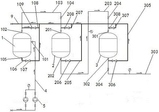
[0034] Such as figure 1 As shown, a skid-mounted water injection well circulation well cleaning device includes an oil sludge water separation tank 1, an integrated coarse filter tank 2 connected with the oil sludge water separation tank 1, and an integrated fine filter tank connected with the integrated coarse filter tank 2 3. There is a first water inlet 101 on the side wall of the sludge-water separation tank 1, a first water outlet 102 on the top, a second water inlet 201 on the top of the integrated coarse filter tank 2, and a second outlet on the bottom. The water port 202, the top of the integrated fine filter tank 3 is provided with a third water inlet 301, and the bottom end is provided with a third water outlet 302;
[0035] The first water inlet 101 is connected to the wellhead drainage pipeline 4, the first water outlet 102 and the second water inlet 201 are connected through the first pipeline 103, and the second water outlet 202 and the third water inlet 301 are ...
Embodiment 2
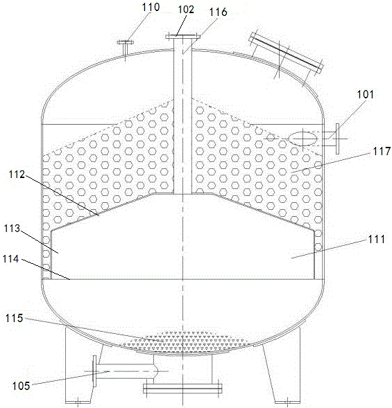
[0041] On the basis of Example 1, it needs to be further explained that, as figure 2 As shown, the sludge water separation tank 1 is provided with a silt barrel 111 coaxial with the oil sludge water separation tank 1, and the surface of the silt bucket 111 is provided with a plurality of flow holes, and the bottom of the silt bucket 111 is a sand collecting tank. Zone 115, the top of the sediment bucket 111 is covered with an oil removal filler layer 117, and the top axial center of the sediment bucket 111 is connected with a water outlet conduit 116, and the water outlet conduit 116 extends out of the top of the sludge-water separation tank 1 and the second water outlet. 202 connected.
[0042] Concretely, the sludge water separation tank 1 is provided with a sediment bucket 111 coaxial with the sludge water separation tank 1, and the sediment bucket 111 consists of a top cover 112 with a trapezoidal cross section and a rectangular retaining ring with a cross section from to...
Embodiment 3
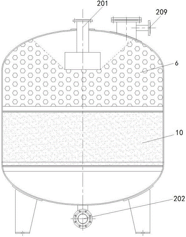
[0046] On the basis of Example 2, such as image 3 , Figure 4 As shown, in order to further purify the well washing water so that it reaches the standard of recycling, the integrated coarse filter tank 2 and the integrated fine filter tank 3 are all provided with a filter material layer 10 along the radial direction, and the filter material layer 10 The top is covered with an oil removal filter material layer 6.
[0047] The well washing water enters the integrated coarse filter tank 2 through the water outlet conduit 116 after passing through the vortex, micro vortex, inertia, centrifugal force, buoyancy and gravity of the oil sludge water separation tank 1, and enters the integrated coarse filter tank 2. After the filter material layer 10 absorbs and removes the large particle impurities in the well washing water, the oil and gas in the well washing water are removed through the oil removal filter material layer 6, and then enters the integrated fine filter tank 3, and in ...
PUM
 Abstract
Description
Claims
Application Information
 - R&D
- Intellectual Property
- Life Sciences
- Materials
- Tech Scout
- Unparalleled Data Quality
- Higher Quality Content
- 60% Fewer Hallucinations
Browse by: Latest US Patents, China's latest patents, Technical Efficacy Thesaurus, Application Domain, Technology Topic, Popular Technical Reports.
© 2025 PatSnap. All rights reserved.Legal|Privacy policy|Modern Slavery Act Transparency Statement|Sitemap|About US| Contact US: help@patsnap.com


