A damping vibration isolator for power facilities

A technology for power facilities and vibration isolators, which is applied in the direction of non-rotational vibration suppression, can solve the problems of easy tearing and vibration isolator failure, and achieve the effects of simple production, improved energy consumption capacity, and improved damping

Active Publication Date: 2017-11-03
CHINA ELECTRIC POWER RES INST +2
View PDF4 Cites 0 Cited by
  • Summary
  • Abstract
  • Description
  • Claims
  • Application Information

AI Technical Summary

Problems solved by technology

When the bearing is under compression, the steel plate constrains the lateral deformation of the rubber sheet, so that the deformation is small and the vertical stiffness is large; when the laminated bearing is stretched under tension, the contact surface between the thin rubber sheet and the thin steel plate is easy Tearing occurs, causing the isolator to fail

Method used


Image

  • A damping vibration isolator for power facilities
  • A damping vibration isolator for power facilities
  • A damping vibration isolator for power facilities

Examples


Embodiment 1

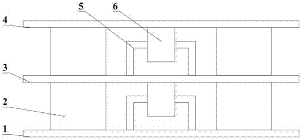
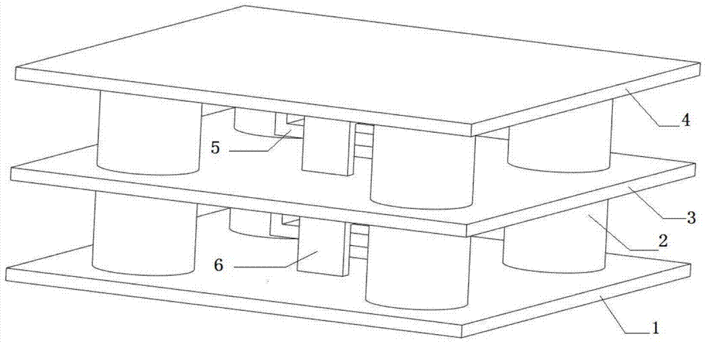
[0041] Such as figure 1 As shown, a damping vibration isolator for power facilities, the vibration isolator includes a top plate 4, a middle plate 3, and a bottom plate 1 arranged coaxially and parallel in the horizontal direction, and a support 2 and a limiter are arranged between every two adjacent plates. pieces.

[0042] Preferably, the support 2 includes a composite layer in which a cylindrical lead alloy core and covered rubber sheets and thin steel plates are arranged alternately.

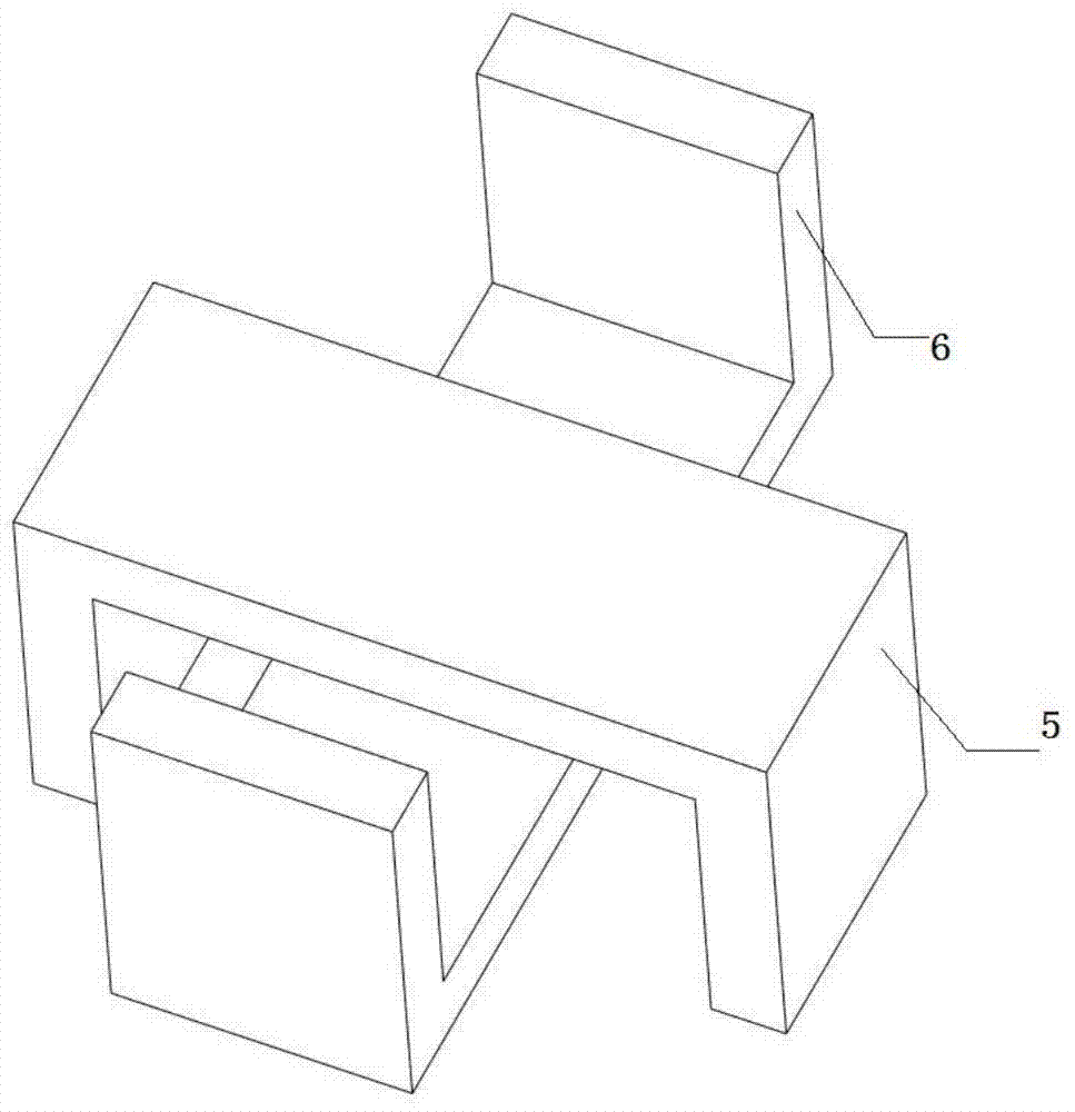
[0043] Preferably, the limiter includes an inverted U-shaped lower limiter 5 and a U-shaped upper limiter 6 respectively correspondingly arranged on the upper and lower surfaces of two adjacent plates where the upper and lower surfaces perpendicularly intersect, and the limiter is arranged inside the support 2 .

[0044] The limit block is made by welding steel plates.

[0045] Preferably, the top plate 4, the middle plate 3, and the bottom plate 1 adopt square steel plates with correspond...

Embodiment 2

[0055] The structure is consistent with Example 1, and the lead alloy core is made of the following components in terms of mass percentage: 0.10% aluminum, 2% antimony, 0.1 calcium, 1% strontium, and the balance is lead and unavoidable impurities.

[0056] Connect the center of support 22 to form a square, and the center of the square is located on the axis of the plate; the distance between the intersection of the axis of support 22 and the plate and the nearest apex of the plate is 1 / 5 of the diagonal length of the plate.

Embodiment 3

[0058] The structure is consistent with Example 1, and the lead alloy core is made of the following components in terms of mass percentage: 0.15% aluminum, 2% antimony, 3% calcium, 1% strontium, and the balance is lead and unavoidable impurities.

[0059] Connect the center of support 22 to form a square, and the center of the square is located on the axis of the plate; the distance between the intersection of the axis of support 22 and the plate and the nearest apex of the plate is 1 / 9 of the diagonal length of the plate.


PUM


Abstract

The invention provides a damping vibration isolator for electric facilities. The vibration isolator comprises a top plate, a middle plate and a bottom plate arranged coaxially and parallel in the horizontal direction, and a support and a limiting member are arranged between every two adjacent plates. The vibration isolator is equipped with a vertical limit device to limit the tensile displacement of the laminated support, avoiding the tensile damage of the support due to the stretching distance exceeding its maximum tensile limit, and prolonging the service life of the vibration isolator .

Description

technical field [0001] The invention relates to a shock isolation device, in particular to a damping vibration isolator for electric facilities. Background technique [0002] Power facilities in earthquake-prone areas not only need to have good process layout, but also need to have good seismic performance. Installing shock absorbers in power facilities can effectively improve the seismic performance of power facilities. [0003] Seismic isolation devices that isolate a structure from its foundation include vibration isolators and energy-dissipating dampers. The vibration isolator has the ability to bear the load transmitted by the upper structure and resist the stiffness. The smaller the horizontal stiffness of the vibration isolator, the larger the relative displacement between the superstructure and the foundation, while the relationship between the acceleration response between layers and the displacement of the isolation layer is opposite. [0004] At present, the wi...

Claims


Application Information

Patent Timeline
Patent Type & Authority Patents(China)
IPC IPC(8): F16F15/08
Inventor 张谦卢智成孙宇晗吉晔钟珉刘振林朱祝兵高坡林森李圣
Owner CHINA ELECTRIC POWER RES INST
Why Eureka
Try Eureka