Closed adiabatic air cooler

An air cooler and heat insulation technology, which is applied in the direction of water shower cooler, direct contact heat exchanger, heat exchanger type, etc., can solve the problems of affecting the heat transfer effect of the tube bundle, wasting electric energy and water resources, and unable to adjust the temperature , to improve the heat transfer effect, reduce water consumption, and meet the heat transfer requirements

Active Publication Date: 2018-10-12
酷仑冷却技术(上海)有限公司
View PDF7 Cites 0 Cited by
  • Summary
  • Abstract
  • Description
  • Claims
  • Application Information

AI Technical Summary

Problems solved by technology

The residue after the water evaporation of the dry-wet combined air cooler will adhere to the root of the finned tubes, resulting in fouling of the heat exchange coil, which will affect the heat exchange effect of the tube bundle after a period of use
Existing air coolers cannot be adjusted according to the external climatic conditions and the temperature of the fluid to be cooled. In transition seasons or cold seasons, the air coolers also run at full capacity, wasting electricity and water resources

Method used


Image

  • Closed adiabatic air cooler
  • Closed adiabatic air cooler
  • Closed adiabatic air cooler

Examples


Embodiment 1

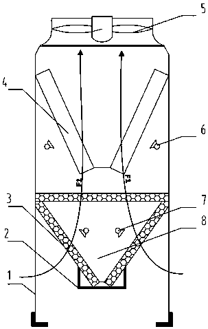
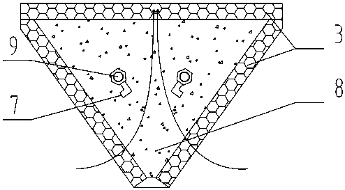
[0026] In the transitional season when the temperature and humidity of the external environment are moderate, the air cooler is in the adiabatic humidifying air mode. At this time, the fan 5 and the atomizing nozzle 7 are in the working state, and the spraying nozzle 6 is in the non-working state. See figure 2 , figure 2 It is a schematic diagram of the adiabatic chamber of the air cooler. The pipe 9 of the atomizing nozzle 7 circulates city tap water for the atomizing nozzle 7 to spray the water. , so that the temperature of the air outlet from the adiabatic chamber is reduced to the wet bulb temperature close to the ambient air. At this time, the low-temperature humid air at the outlet of the adiabatic chamber flushes the heat exchanger tube bundle, which increases the heat exchange temperature difference of the fluid at the heat exchanger and effectively improves the Compared with the spray evaporative cooling mode, the water consumption and the power consumption of the p...

Embodiment 2

[0028] When the temperature and humidity of the external environment are high, the air cooler is in the spray evaporative cooling working mode. At this time, the fan 5 and the spray nozzle 6 are in a working state, the atomizing nozzle 7 is in a non-working state, and the spray nozzle 6 is directed to the fins. The sheet-tube heat exchanger 4 is sprayed with spray water, so that the outer wall of the heat exchanger tube is covered with a water film. The heat is used to cool the circulating fluid in the pipe, and the spray water outside the pipe wall that has not been evaporated in the future flows into the water collection tank. The water in the water collection tank continues to supply water to the spray device through the circulating water pump to reduce water consumption. The spray evaporative cooling mode is suitable for the meteorological conditions of high temperature and high humidity to meet the requirements of heat exchange.

Embodiment 3

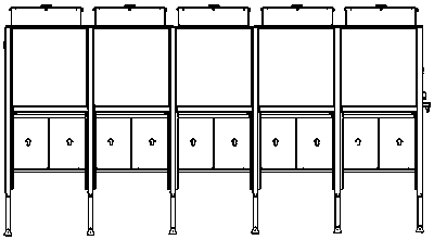
[0030] refer to image 3 , 4, image 3 , 4 is a combination diagram of ten air cooler modules of the present invention. The air cooler of the present invention is a modular device, and the air cooler modules can be combined and used according to different heat exchange requirements.


PUM


Abstract

The invention relates to a closed heat insulation air cooler which comprises an upper heat exchange chamber and a lower heat insulation chamber, wherein finned tube heat exchangers and spraying nozzles are mounted in the upper heat exchange chamber; the finned tube heat exchangers are arranged in a V-shaped manner; the lower heat insulation chamber comprises three corrugated fiber moistening boards which are arranged in an encircling manner to form a cavity; the cavity takes the shape of an inverted triangle, so as to form air intake surfaces, used for enlarging the air intake filtering surfaces and improving adiabatic humidifying and cooling effects, on two sides of a V-shaped structure. The air inlet of the air cooler is V-shaped, so as to enlarge the air intake area and improve the supply air rate of the air cooler, and further improve the integral heat exchange effect of the air cooler. The closed heat insulation air cooler comprises four working modes, namely a spraying evaporation cooling mode, an adiabatic humidifying evaporation cooling mode, a dry cooling mode and a natural cooling mode, which are controlled automatically through an electric control device, so that the air cooler can be in an optimal economical operation mode all the while, and electrical energy and water resources are saved.

Description

technical field [0001] The invention relates to a closed adiabatic air cooler, which uses air to cool the heat flow medium, and is mainly used for cooling the process circulating fluid of heating equipment such as industrial electric furnaces, power supplies and motors. Background technique [0002] Existing air coolers mainly include dry air coolers and dry-wet combined air coolers. Dry air coolers use ambient air as the cooling medium and rely on finned tubes to expand the heat transfer area to strengthen the heat transfer outside the tubes. The air temperature rise after traversing the finned tube takes away heat and achieves the purpose of cooling the fluid in the tube. It is characterized by simple operation and convenient use, but the temperature of the heat flow outlet in the tube depends on the air dry bulb temperature. Cooling does nothing. In order to make up for the shortcomings of dry air coolers, dry and wet combined air coolers have emerged. The working mechan...

Claims


Application Information

Patent Timeline
Patent Type & Authority Patents(China)
IPC IPC(8): F28C1/14F28F25/06F28F27/00
Inventor 涂淑平郭凤朝
Owner 酷仑冷却技术(上海)有限公司
Why Eureka
Try Eureka