Direct-current power flow controller suitable for multi-terminal direct-current transmission system

A DC power flow and power transmission system technology, applied in the field of power electronics, can solve problems such as unfavorable system operation, impact on the service life of capacitors, voltage fluctuations at ports, etc., and achieve the effect of simple circuit structure and fewer switching devices

Active Publication Date: 2015-12-16
SOUTHEAST UNIV
View PDF2 Cites 11 Cited by
  • Summary
  • Abstract
  • Description
  • Claims
  • Application Information

AI Technical Summary

Problems solved by technology

However, the current flow controller scheme proposed by CDBarker et al. only controls the power flow by frequently connecting a capacitor to two different lines. The capacitor is frequently charged and discharged, which will have an impact on the service life of the capacitor. Therefore, the voltage at the input port will also fluctuate, which is also detrimental to the operation of the system
In addition, the inter-line DC power flow controller scheme proposed by Associate Professor Chen Wu et al. is to connect a capacitor in series in each of the two lines, and control the power flow through the flow of power between the two lines. However, this topology is limited by the flow direction of the line power flow. , when the power flow of the line is reversed, the power flow controller cannot work

Method used


Image

  • Direct-current power flow controller suitable for multi-terminal direct-current transmission system
  • Direct-current power flow controller suitable for multi-terminal direct-current transmission system
  • Direct-current power flow controller suitable for multi-terminal direct-current transmission system

Examples


Embodiment 1

[0057] Embodiment 1 is to make the power P1 of VSC1 injection system jump into 0 by 300MW, maintain I 23 It is unchanged at 0.2kA. Figure 9 The current waveform of the transmission line is given, Figure 10 gives the capacitor voltage V c1 and V c2 the waveform, Figure 11 gives the port voltage V 1 and V 2 waveform. Depend on Figure 9 It can be seen that the current I 23 Before and after the power loss of VSC1, it was stable at a given value of 0.2kA, and due to the loss of VSC1 power, the port voltage and capacitor voltage changed accordingly after 4s. The simulation results show that the power flow controller can still work normally when a certain VSC exits the DC system, and has good stability.

Embodiment 2

[0058] Embodiment 2 is to make the current I 23 Inversion, from 0.2kA to -0.2kA. Figure 12 The current waveform of the transmission line is given, Figure 13 gives the capacitor voltage V c1 and V c2 the waveform, Figure 14 gives the port voltage V 1 and V 2 waveform. Depend on Figure 12 It can be seen that the power flow controller of the present invention can realize the reversal of the line flow

[0059] Topology promotion

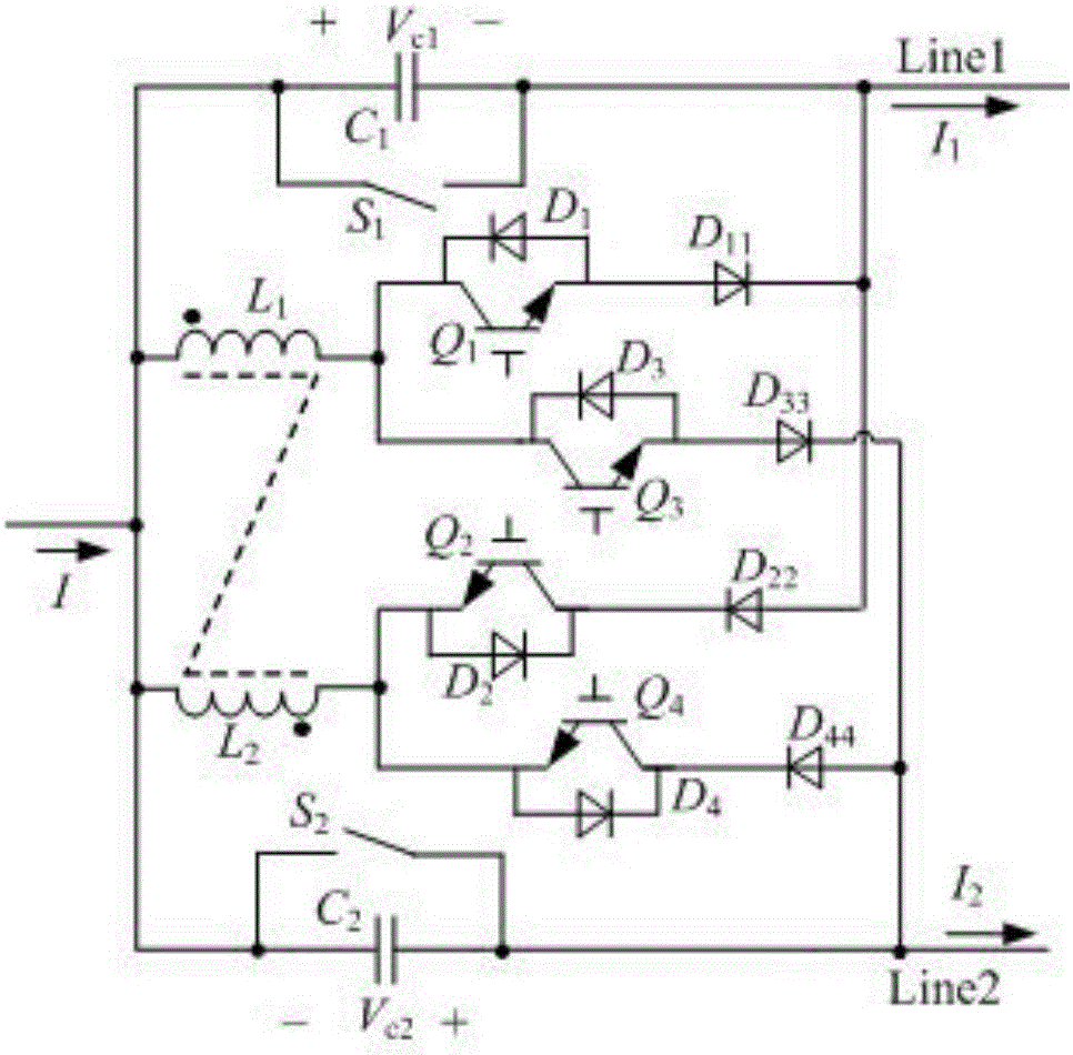
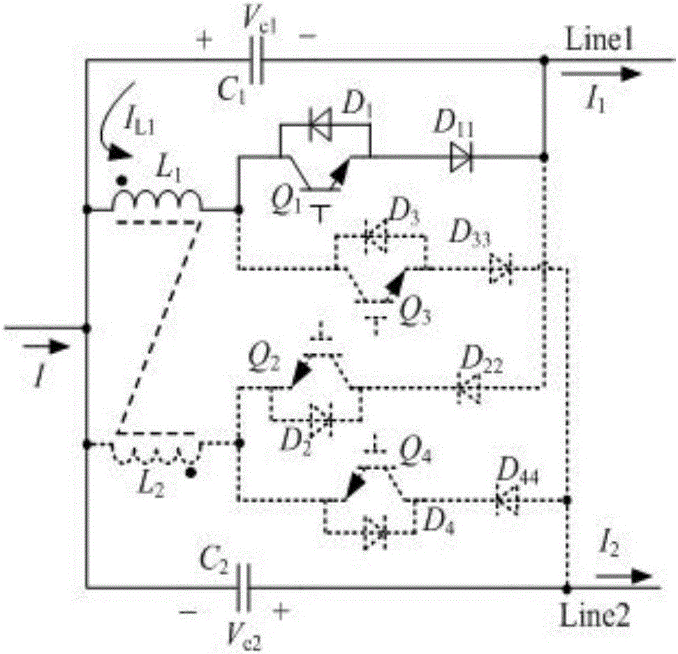
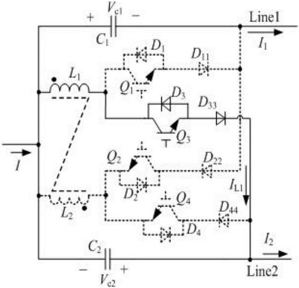
[0060] According to the above analysis, the DC power flow controller of the present invention can carry out topology promotion, such as Figure 15 shown. and figure 1 compared to, Figure 15 Two inductors are added to the DC power flow controller, and the four inductors are all wound on the same magnetic core to form a coupled inductor. Its working principle is the same as that of the switching mode and figure 1 The power flow controllers shown are the same and will not be repeated here. The application of the DC power flow controller i...


PUM


Abstract

The invention provides a direct-current power flow controller suitable for a multi-terminal direct-current transmission system. The multi-terminal direct-current transmission system comprises a direct-current transmission port and two transmission lines, wherein the transmission lines are connected with the direct-current transmission port in parallel; the direct-current power flow controller comprises a capacitor C1, a capacitor C2, a by-pass switch S1 and a by-pass switch S2; the capacitor C1 is connected to the first transmission line as an adjustable voltage source Vc1 in series; the capacitor C2 is connected to the second transmission line as an adjustable voltage source Vc2 in series; the by-pass switch S1 is connected with the adjustable voltage source Vc1 in parallel; the by-pass switch S2 is connected with the adjustable voltage source Vc2 in parallel; when both the by-pass switch S1 and the by-pass switch S2 are switched on, the direct-current power flow controller is bypassed and does not participate into direct-current power flow adjustment; and when both the by-pass switch S1 and the by-pass switch S2 are switched off the direct-current power flow controller participates into direct-current power flow adjustment, so that reverse rotation of line power flow can be achieved.

Description

technical field [0001] The invention relates to a direct current flow controller, which belongs to the technical field of power electronics and is mainly used in multi-terminal direct current transmission occasions. Background technique [0002] With the continuous development of large-scale new energy power, offshore wind power generation technology has become more and more mature. Due to the loose distribution of offshore wind farms and the distribution of onshore load centers in different regions, the traditional AC power grid is limited by economic and technical conditions when receiving and transmitting large-scale and long-distance offshore wind power. Compared with high voltage alternating current (high voltage direct current, HVDC) transmission technology, high voltage direct current transmission technology is attracting the attention of researchers because of its advantages such as good economy and long transmission distance. [0003] The early form of HVDC transmi...

Claims


Application Information

Patent Timeline
Patent Type & Authority Applications(China)
IPC IPC(8): H02J1/10
Inventor 陈武朱旭
Owner SOUTHEAST UNIV
Why Eureka
Try Eureka