A vacuum melting device for non-oxide optical glass

A vacuum melting, optical glass technology, applied in glass production, glass furnace equipment, glass manufacturing equipment and other directions, can solve the problems affecting the non-oxide optical glass yield product stability, glass homogenization effect and production efficiency is not high, wire Or the brush is easily damaged, etc., to improve the efficiency of vacuum melting, improve production efficiency and product yield, and avoid abnormal power failure.

Active Publication Date: 2018-01-16
HUBEI NEW HUAGUANG NEW INFORMATION MATERIALS CO LTD
View PDF5 Cites 1 Cited by
  • Summary
  • Abstract
  • Description
  • Claims
  • Application Information

AI Technical Summary

Problems solved by technology

In terms of swing furnaces, the prior art adopts the overall swing method of the swing furnace, but the overall swing method will not only increase the excess load, increase the power consumption of the motor, but also make the wires connected to the swing furnace body Or the brush is more easily damaged, that is, it is more likely to cause abnormal production, thereby affecting the yield rate and product stability of non-oxide optical glass production. In addition, due to the limitation of wires or brushes, the swing angle of the existing swing furnace is 180° Within, the homogenization effect and production efficiency of glass are not high

Method used


Image

  • A vacuum melting device for non-oxide optical glass
  • A vacuum melting device for non-oxide optical glass

Examples


Embodiment Construction

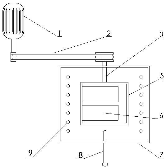
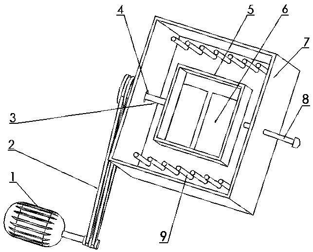
[0012] Such as figure 1 , 2 As shown, the invention provides a vacuum melting device for non-oxide optical glass, which realizes vacuum melting of non-oxide optical glass. The invention consists of two parts, a smelting furnace body and a swing device. Among them, the smelting furnace body includes a furnace body 7, a heating element 9 and a vacuum melting container 6, a through hole is arranged on one side of the furnace body 7, and the heating element 9 is made of silicon carbide rod or resistance wire, and can be arranged horizontally or vertically. Or the circle is installed between the swing box 5 and the furnace body 7, which is heated by indirect heating, and is suitable for non-oxide optical glass with a low melting point. Furnace body 7 is built with unshaped lightweight refractory bricks, and the outside of the refractory material is welded by steel to form a furnace structure. After the smelting furnace body is repaired, the swing box 5 is placed in the center of...


PUM


Abstract

The name of the invention is a vacuum melting device for non-oxide optical glass. It belongs to the technical field of glass production equipment. It mainly solves the problems that the overall swing of the existing swing furnace has a heavy swing body, power consumption of the motor, and easy production abnormalities, thereby affecting the production yield and product stability. Its main features are: the smelting furnace body includes a furnace body, heating elements and a vacuum melting container, and a through hole is arranged on one side of the furnace body; the swing device is composed of a motor, a power transmission belt, a swing shaft and a swing box; the swing box is located in the furnace In the body, the swing shaft passes through the through hole, one end of the swing shaft is connected to the swing box, the other end of the swing shaft is connected to one end of the power transmission belt, and the other end of the power transmission belt is connected to the motor; the vacuum melting container is installed in the swing box. The invention has the characteristics of improving vacuum smelting efficiency, making production more stable and reducing power consumption, and is mainly used for vacuum smelting of non-oxide optical glass.

Description

technical field [0001] The invention belongs to the technical field of glass production equipment, in particular to a vacuum melting device for non-oxide optical glass. Background technique [0002] The existing general vacuum smelting technology is to put the raw materials into the smelting container (ampoules) after batching according to the formula, and then use a vacuum pump to pump the smelting container (ampoules) into a relative vacuum, and use rock swing method for homogenization during the smelting process carried out in a manner. In terms of swing furnaces, the prior art adopts the overall swing method of the swing furnace, but the overall swing method will not only increase the excess load, increase the power consumption of the motor, but also make the wires connected to the swing furnace body Or the brush is more easily damaged, that is, it is more likely to cause abnormal production, thereby affecting the yield rate and product stability of non-oxide optical gl...

Claims


Application Information

Patent Timeline
Patent Type & Authority Patents(China)
IPC IPC(8): C03B5/18
CPCY02P40/57
Inventor 霍金龙杨爱清戎俊华胡向平杨谧玲
Owner HUBEI NEW HUAGUANG NEW INFORMATION MATERIALS CO LTD
Why Eureka
Try Eureka