Domestic sewage separation and classification power generation system for high-rise buildings and its control method

A technology for domestic sewage and high-rise buildings, applied in construction, sustainable buildings, water supply installations, etc., can solve the problems of waste of organic fertilizer, reduced power generation of generators, unstable power generation current, etc., to improve mechanical efficiency and reduce pipelines. Blockage, the effect of solving system blockage

Inactive Publication Date: 2017-05-03
JIANGSU UNIV
View PDF7 Cites 0 Cited by
  • Summary
  • Abstract
  • Description
  • Claims
  • Application Information

AI Technical Summary

Problems solved by technology

[0004] 1. Mainly use unseparated domestic sewage to directly generate electricity. Since domestic sewage is discontinuous and directly used, there will be problems of unstable power generation current and poor power generation quality. It is difficult to ensure long-term continuous and stable power generation, and most The power generation system does not take into account the use of the mechanical energy of the rainwater on the roof of high-rise buildings and the use of relatively clean rainwater as the water source for system flushing
[0005] 2. Although the solid and semi-solid pollutants in domestic sewage are separated, the separated pollutants are directly discharged into public sewage pipes, which greatly wastes organic fertilizers and increases the workload of sewage treatment plants
[0006] 3. Since the cleaning and cleaning of the sewage pipes are not involved, the dirt in the sewage pipes is very easy to stick to the pipe wall, resulting in smaller pipe diameters and reduced power generation of the generator, which in turn reduces the mechanical efficiency of the power generation system

Method used


Image

  • Domestic sewage separation and classification power generation system for high-rise buildings and its control method

Examples


Embodiment Construction

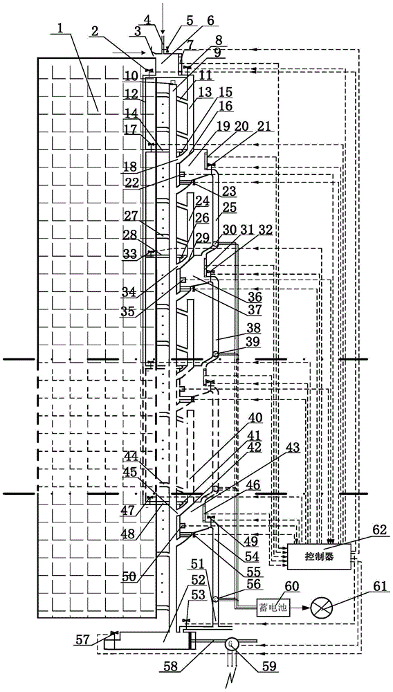
[0024] like figure 1 As shown, the high-rise building 1 itself is equipped with a vertical main sewage pipe 9 from the top to the bottom of the high-rise building 1, and the domestic sewage of each floor household where the high-rise building 1 lives is discharged to the main sewage discharge pipe through the household sewage discharge pipe of this floor. Tube 9. According to the actual number of floors of the high-rise building 1, all household sewage discharge pipes of the high-rise building 1 are divided into several levels from top to bottom, and each level of sewage discharge pipe is composed of multi-layer household sewage discharge pipes. Like this, all resident domestic sewage discharge pipes are successively divided into first-level household sewage discharge pipes 11 of each floor, second-level domestic sewage discharge pipes 27 of each floor households, and until the last level of household sewage discharge pipes of each floor from top to bottom. Tube 44. The numb...


PUM


Abstract

The invention discloses a domestic sewage separation and classification power generation system of a high-rise building and a control method thereof. A rainwater storage tank is placed on the roof of the high-rise building, and the rainwater storage tank is connected to a general cleaning pipe vertically from top to bottom through a general cleaning port opened at the bottom. The top of the rainwater storage tank is connected to the top of the vertical first-level sewage collection pipe through the drainage port opened at the bottom; the sewage collection pipes of all levels, the water tanks of all levels and the drainage pipes of the water tanks of all levels are arranged sequentially under the rainwater storage tank from top to bottom. The drainage pipes of each level of water tank are connected in series between the front and rear water tanks. Except that the top of the first-level sewage collection pipe is connected to the rainwater storage tank at the top, the top ports of the other sewage collection pipes at all levels are closed and the bottoms are closed. Connect the top of the water tank of the same level, the bottom of each level of water tank is connected to the main sewage pipe through the sewage outlet, and is connected to the top inlet of the water tank drain pipe of the same level through the drain outlet; The collected rainwater is used for power generation, realizing the complementary energy of the two kinds of water.

Description

technical field [0001] The invention belongs to the field of energy-saving technology for high-rise buildings with more than 7 to 10 floors and the treatment field of domestic sewage, and in particular relates to a separation system and a power generation system for domestic sewage in high-rise buildings. Background technique [0002] With the continuous increase of urban population and the increasing requirement of human beings for the quality of life, issues such as the utilization of land resources, energy demand and environmental protection have been paid more and more attention by countries all over the world. High-rise buildings have become an important part and an important development direction of current and future urban buildings because of their significant advantages such as effectively alleviating construction land and strong comprehensive capabilities. However, high-rise buildings have a large population density, consume a lot of energy, and generate a huge amo...

Claims


Application Information

Patent Timeline
Patent Type & Authority Patents(China)
IPC IPC(8): E03C1/12E03C1/122E03B3/02F03B13/00
CPCY02A20/108Y02B10/50
Inventor 郭玉琴李富柱王存堂陈龙
Owner JIANGSU UNIV
Why Eureka
Try Eureka