

Turbine blade of blade top rib wing structure
A technology of turbine blade and wing structure, which is applied in the direction of supporting components of blades, machines/engines, mechanical equipment, etc., and can solve problems such as thermal corrosion of blade tops, reduction of heat transfer performance of blade tops, and flow loss
- Summary
- Abstract
- Description
- Claims
- Application Information
AI Technical Summary
Problems solved by technology
Method used
Image

Examples
Embodiment Construction
[0030] The present invention is described in detail below in conjunction with accompanying drawing and embodiment:
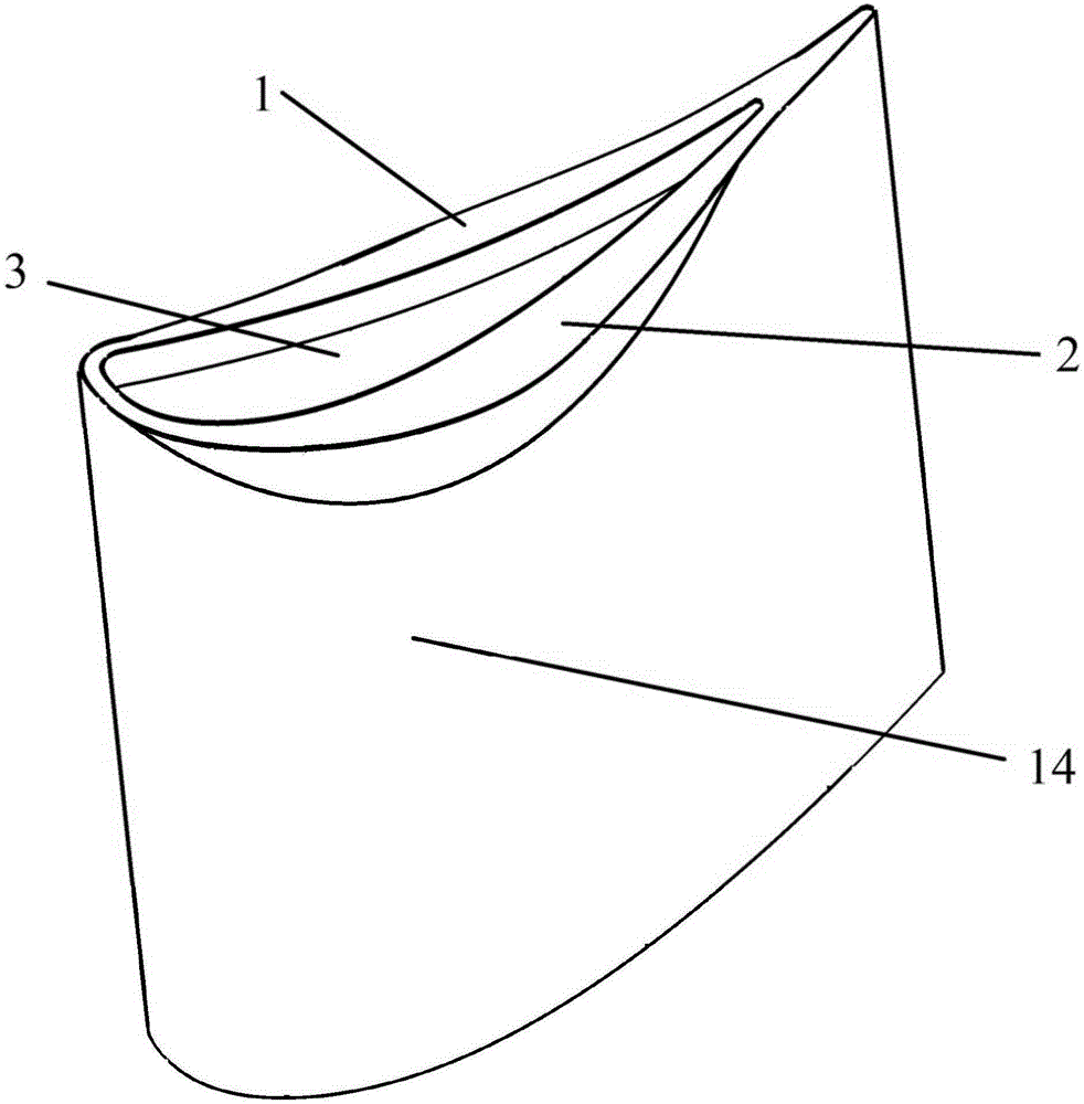
[0031] Such as figure 1 As shown, the blade tip structure of a new type of turbine rotor blade includes a blade pressure side winglet 1 and a blade suction side winglet 2, and the blade pressure side winglet 1 and the blade suction side winglet 2 are formed Cavity 3 in the middle of the leaf tip.
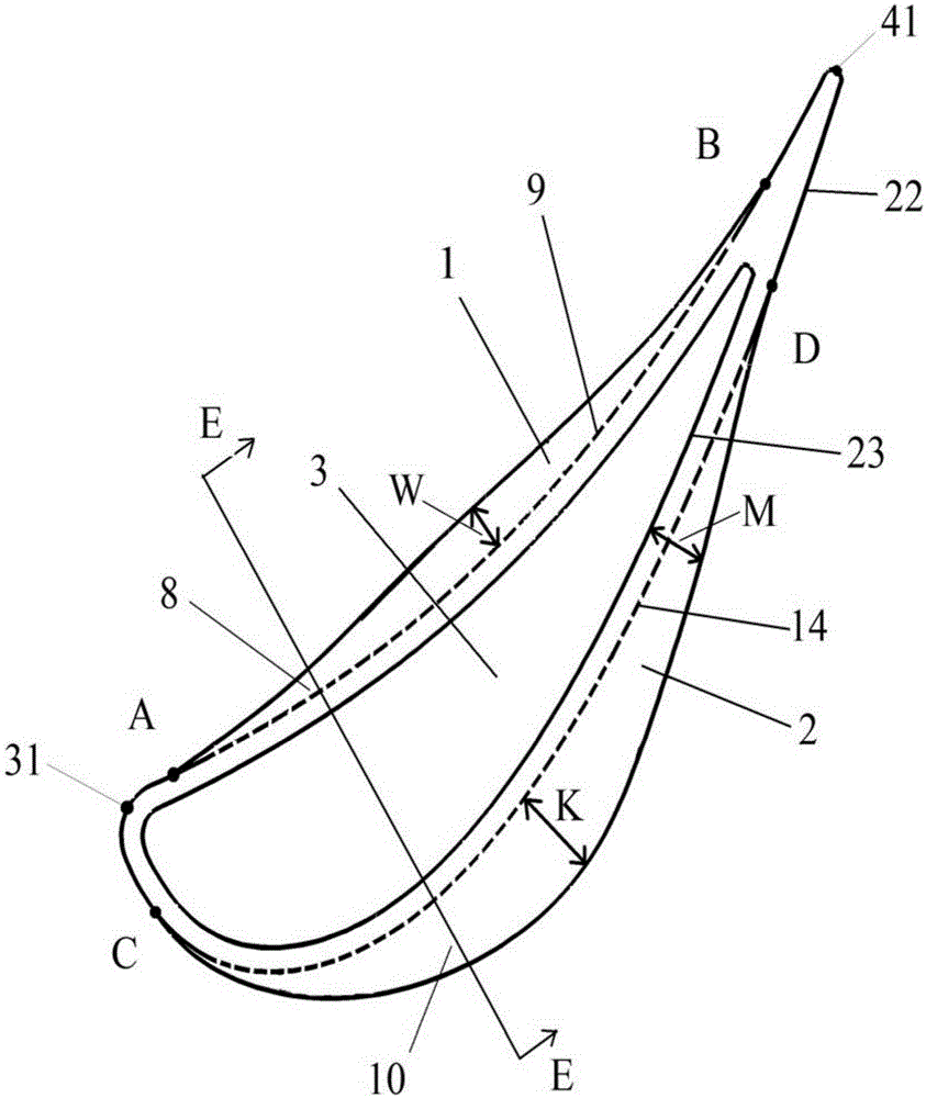
[0032] Such as figure 2 As shown, the starting point A of the pressure surface winglet 1 is close to the leading edge 31 of the blade, and the ending point B is close to the trailing edge 41 of the blade; the starting point A of the pressure surface is located on the suction surface, and the distance from the leading edge 31 of the blade is 0%-50% The length of the pressure surface, the end point B of the pressure surface is located on the pressure surface, and the distance from the blade trailing edge 41 is 40%-90% of the pressure surface length.
[0033] The wid...
PUM
 Abstract
Description
Claims
Application Information