
Floating liquefied natural gas regasification system for low-temperature water area

A liquefied natural gas and floating technology, which is applied in fixed-capacity gas storage tanks, container discharge methods, gas/liquid distribution and storage, etc., can solve problems such as shortening the service life of equipment, hidden safety hazards of leakage, and corrosion of heat exchangers. Achieve the effects of high comprehensive energy utilization rate, continuous and safe gas supply, and corrosion prevention

Active Publication Date: 2015-12-23
CNOOC GAS & POWER GRP
View PDF6 Cites 2 Cited by
  • Summary
  • Abstract
  • Description
  • Claims
  • Application Information

AI Technical Summary

Problems solved by technology

[0008] Existing floating LNG regasification systems are generally only suitable for sea areas with seawater temperatures above 8°C, and have certain limitations for the above-mentioned hydroclimatic conditions in the Bohai Sea, Yellow Sea, and East China Sea: on the one hand, seawater temperatures are lower than 8°C, and now Some floating liquefied natural gas regasification systems cannot be used; on the other hand, for seawater with a lot of sand and poor water quality, it will cause corrosion to the heat exchanger, shorten the service life of the equipment, and pose a safety hazard of leakage

Method used


Image

  • Floating liquefied natural gas regasification system for low-temperature water area

Examples


Embodiment Construction

[0017] The present invention will be described in detail below in conjunction with the accompanying drawings. However, it should be understood that the accompanying drawings are provided only for better understanding of the present invention, and they should not be construed as limiting the present invention. In the description of the present invention, it should be understood that the terms "first", "second" and so on are only used for the purpose of description, and should not be understood as indicating or implying relative importance.

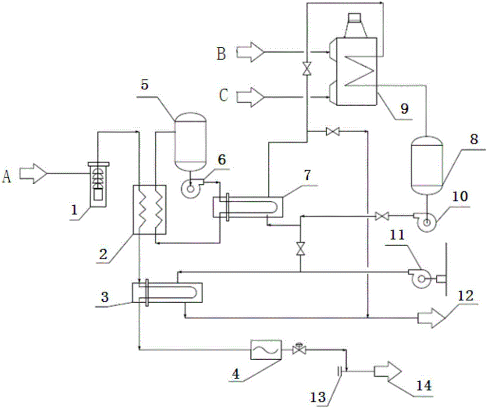
[0018] Such as figure 1 As shown, the floating liquefied natural gas regasification system for low temperature waters of the present invention includes a LNG / NG conversion structure, an intermediate medium (IF) loop structure, a heating medium (HM) loop structure and a seawater circulation structure;

[0019] The LNG / NG conversion structure includes an LNG high-pressure pump 1, the inlet of the LNG high-pressure pump 1 is connected to the ...


PUM


Abstract

The invention relates to a floating liquefied natural gas regasification system for a low-temperature water area. The floating liquefied natural gas regasification system for the low-temperature water area is characterized in that the floating liquefied natural gas regasification system comprises a liquefied natural gas (LNG) / natural gas (NG) conversion structure, an intermediate medium loop structure, a heating medium backflow structure and a seawater circulating structure. An intermediate medium heater obtains heat from seawater or a heat exchanger (HM), and the seawater is used as a heat source most time when the inlet temperature of the seawater is higher than 8 DEG C; when the temperature of the seawater is lower than 8 DEG C, the HM replaces the seawater to serve as the heat source through the intermediate medium heater. According to the floating liquefied natural gas regasification system for the low-temperature water area, heating media are introduced under the low-temperature seawater working condition, the quantity and form of the heating media can be changed according to different sea areas, in this way, the system can be used in sea areas under various seawater working conditions, is suitable for all sea areas in China and similar sea areas in foreign countries, is flexibly applied to various seawater working conditions, and not only is applicable to the low-temperature water area, but also can prevent the intermediate medium heater from being corroded. By the adoption of the floating liquefied natural gas regasification system for the low-temperature water area, stable production in the water areas in the north of China can be achieved, and continuous safe gas supply is achieved.

Description

technical field [0001] The invention relates to a floating liquefied natural gas (LNG) regasification system, in particular to a floating liquefied natural gas regasification system suitable for low-temperature waters such as the northern seas of China, and capable of adapting to sea areas with different seawater working conditions and water quality conditions system. Background technique [0002] As the country's demand for energy continues to grow, the introduction of LNG plays an important role in optimizing China's energy structure, effectively solving the dual problems of energy supply security and ecological environment protection, and achieving sustainable economic and social development. The way to receive LNG is generally divided into land and sea. Nowadays, China's economic development has an increasing demand for natural gas, and there are many onshore LNG receiving stations in coastal areas. The resource allocation of LNG receiving stations, offshore floating r...

Claims


Application Information

Patent Timeline
Patent Type & Authority Applications(China)
IPC IPC(8): F17C7/04F17C13/00F17C13/02
Inventor 黄宇屈长龙陈海平胡献文宋坤
Owner CNOOC GAS & POWER GRP
Learn More