Radiator and floor radiation heating loop cascade heat exchange station system and heat gradient utilization method

A radiant heating and radiator technology, applied in hot water central heating systems, heating systems, heating methods, etc., can solve the problem of ineffective use of heat medium temperature, high return water temperature of secondary network, radiator heating and floor radiation High investment of heating and heat exchanger parallel heat exchange station system

Active Publication Date: 2015-12-23
HARBIN INST OF TECH
View PDF8 Cites 13 Cited by
  • Summary
  • Abstract
  • Description
  • Claims
  • Application Information

AI Technical Summary

Problems solved by technology

[0004] The purpose of the present invention is to solve the problem that the existing radiator heating and floor radiant heating secondary network parallel heat exchange station system and the radiator heating and floor radiant heating heat exchanger parallel heat exchange station system do not effectively use the temperature of the heat mediu

Method used


Image

  • Radiator and floor radiation heating loop cascade heat exchange station system and heat gradient utilization method
  • Radiator and floor radiation heating loop cascade heat exchange station system and heat gradient utilization method
  • Radiator and floor radiation heating loop cascade heat exchange station system and heat gradient utilization method

Examples


specific Embodiment approach 1

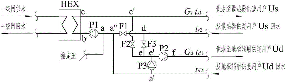
[0087] Embodiment 1: A radiator and floor radiant heating loop cascaded heat exchange station system in this embodiment includes a heat exchanger unit HEX, a secondary network circulating water pump unit P1, a secondary network circulating water pump unit P2, and a water mixing pump Unit P3, control valve unit F1, control valve unit F2 and control valve unit F3; image 3 ;

[0088] One end c of the water supply pipe cc' of the heat exchanger unit is connected to the heat exchanger unit HEX, and the other end c' of the water supply pipe cc' of the heat exchanger unit is respectively connected to the water supply pipe of the radiator heating loop and the water supply pipe of the floor radiant heating loop ee';

[0089] Wherein, the other end c' of the water supply pipe cc' of the heat exchanger unit is connected to the water supply pipe ee' of the floor radiant heating loop through the control valve unit F2;

[0090] The water supply pipe of the radiator heating loop is connec...

specific Embodiment approach 2

[0099] Specific embodiment 2. The difference between this embodiment and specific embodiment 1 is that one end a of the return pipe a"a of the heat exchanger unit is connected to the constant pressure equipment of the secondary network through a pipeline.

[0100] Other steps and parameters are the same as those in Embodiment 1.

specific Embodiment approach 3

[0101] Specific Embodiment Three: The heat cascade utilization method of a radiator and floor radiant heating loop cascaded heat exchange station system in this embodiment is characterized in that it is a radiator and floor radiant heating loop cascaded heat exchange station The specific process of the heat cascade utilization method of the system is as follows: image 3 ;

[0102] 1. When the flow G of the radiator heating loop s Equal to the flow G of the radiant floor heating loop d , there are 3 situations:

[0103] 1.1) When the return water temperature of the radiator heating loop is t s2 Equal to the supply water temperature t of the radiant floor heating loop d1 ; The specific process is:

[0104] The water supply of the secondary network reaches the water supply pipe node c of the heat exchanger unit through the heat exchanger unit HEX, from the water supply pipe node c of the heat exchanger unit to the water supply pipe node c' of the heat exchanger unit, and fr...


PUM


Abstract

The invention relates to a radiator and floor radiation heating loop cascade heat exchange station system and a heat gradient utilization method. The system and the method aim to solve the problems that an existing radiator heating and floor radiation heating second-class network parallel heat exchange station system and a radiator heating and floor radiation heating heat exchanger parallel heat exchange station system cannot effectively utilize the temperature of heating media, namely the second-class network return water temperature is high, and the investment of the radiator heating and floor radiation heating heat exchanger parallel heat exchange station system is excessively high. Particularly, the radiator and floor radiation heating loop cascade heat exchange station system comprises a heat exchanger unit, a second-class network circulating water pump unit P1, a second-class network circulating water pump unit P2, a water mixing pump unit P3, a control valve unit F1, a control valve unit F2 and a control valve unit F3. A radiator heating loop and a floor radiation heating loop are connected in series. The system and the method are applied to the field of heat-supply engineering.

Description

technical field [0001] The invention relates to a radiator and floor radiation heating loop cascade heat exchange station system and a heat cascade utilization method. Background technique [0002] With the improvement of people's living standards and high requirements for the comfort of the indoor environment, the application of floor radiant heating is becoming more and more extensive. In the heating system, there are both radiator heating users and floor radiant heating users in the same heat exchange station. universal. my country's "Code for Design of Heating, Ventilation and Air Conditioning for Civil Buildings" stipulates that the water supply temperature of the floor radiant heating system should not exceed 60°C, and the temperature difference between supply and return water should not exceed 10°C; the temperature of water supply for radiator heating should not exceed 85°C, and the temperature difference between supply and return water should not less than 20°C. Due...

Claims


Application Information

Patent Timeline
IPC IPC(8): F24D3/02F24D3/10F24D19/10
Inventor 王芃任盼红单晓芳曹姗姗
Owner HARBIN INST OF TECH
Why Eureka
Try Eureka