
Parameter setting method of bilateral LC type electric field coupling type wireless power transmission (WPT) system constant current output

A technology of electric field coupling and constant current output, which is applied in the direction of output power conversion device, DC power input conversion to DC power output, circuit device, etc., which can solve the problem of large voltage stress of coupling mechanism, excessive voltage stress, and reduction of coupling mechanism Reactive power and other issues, achieve the effect of small voltage stress, reduce cost, and improve transmission power level

Active Publication Date: 2018-03-23
SOUTHEAST UNIV
View PDF5 Cites 9 Cited by
  • Summary
  • Abstract
  • Description
  • Claims
  • Application Information

AI Technical Summary

Problems solved by technology

[0006] The purpose of the present invention is to address the shortcomings of the above-mentioned background technology, and provide a parameter setting method for the constant current output of the bilateral LC type electric field coupled WPT system, which balances the original , The voltage stress of the secondary side compensation network reduces the reactive power of the coupling mechanism, which solves the problem of the large voltage stress of the coupling mechanism of the existing bilateral LC type compensation network and the excessive voltage stress borne by a certain component in the original secondary side compensation network big technical problem

Method used


Image

  • Parameter setting method of bilateral LC type electric field coupling type wireless power transmission (WPT) system constant current output
  • Parameter setting method of bilateral LC type electric field coupling type wireless power transmission (WPT) system constant current output
  • Parameter setting method of bilateral LC type electric field coupling type wireless power transmission (WPT) system constant current output

Examples


Embodiment Construction

[0022] The technical solution of the invention will be described in detail below in conjunction with the accompanying drawings.

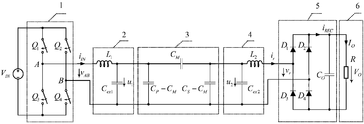
[0023] Bilateral LC type electric field coupled WPT system includes: high frequency full bridge inverter circuit 1, including primary side compensation inductor L 1 and the primary side compensation capacitor C ex1 The primary side LC compensation network 2, the coupling capacitor plate including two emitter plates and two receiving plates 3, including the secondary side compensation inductance L 2 and the secondary side compensation capacitor C ex2 The secondary side LC compensation network 4, the full bridge rectification filter circuit 5. Primary side compensation inductance L 1 One end of the high-frequency full-bridge inverter circuit and the first power tube Q 1 , the third power tube Q 3 The midpoint A of the formed bridge arm is connected, and the primary compensation inductance L 1 The other end of the primary side compensation capaci...


PUM


Abstract

The present invention discloses a parameter setting method of the bilateral LC type electric field coupling type WPT system constant current output, and belongs to the WPT technology field. A system comprises a high-frequency full-bridge inverter circuit, a primary side LC compensation network containing a primary side compensation inductor and a primary side compensation capacitor, a coupling capacitance plate containing two emission polar plates and two reception polar plates, a secondary side LC compensation network containing a secondary side compensation inductor and a secondary side compensation capacitor and a full-bridge rectifying and filtering circuit. The parameter setting method, under the premise of guaranteeing a constant current needed by a load, adjusts the parameters of the primary side and secondary side compensation networks to balance the voltage stresses of the primary side and secondary side compensation networks, so that the system outputs the constant current needed by the load, and the circuit zero approximation reactive circulation and the soft on-off of the switch devices are realized, the own reactive power of the coupling capacitance plate is lowest, the efficiency and the reliability of a WPT system are improved, the cost is reduced, and the transmission power grade is improved.

Description

technical field [0001] The invention discloses a parameter setting method for constant current output of a bilateral LC type electric field coupled WPT system, belongs to the technical field of wireless energy transmission, and is suitable for applications requiring constant current output such as LED power supply and battery charging. Background technique [0002] At present, domestic research hotspots on wireless power transmission (WPT, Wireless Power Transmission) technology mainly focus on the magnetic field coupling method. The electric field coupling uses high-frequency electric field as the energy carrier. When the high-frequency alternating current acts on the emitter plate, an interactive electric field is formed between the emitter plate and the receiver plate to generate a displacement current, which realizes the The energy transmission has the advantages of being able to pass through the metal isolation layer, low electromagnetic radiation, and small size. [0...

Claims


Application Information

Patent Timeline
Patent Type & Authority Applications(China)
IPC IPC(8): H02M3/335H02J50/05
CPCH02J50/05H02M3/33569
Inventor 曲小慧连静
Owner SOUTHEAST UNIV
Learn More