A high-power electromagnetic exploration constant current transmitter and modulation method thereof

A transmitting device and high-power technology, which is applied in the field of resource exploration, can solve problems such as low power factor, current distortion, and large device volume, and achieve the effect of reducing volume, reducing loss and heat generation, and simple topology

Inactive Publication Date: 2017-10-27
BEIJING UNIV OF TECH
View PDF6 Cites 0 Cited by
  • Summary
  • Abstract
  • Description
  • Claims
  • Application Information

AI Technical Summary

Problems solved by technology

[0006] The technical problem to be solved by the present invention is to solve the problem that the output terminal power factor of the generator of the electromagnetic emission device in the prior art is low, the current is easily distorted, and the device volume is large

Method used


Image

  • A high-power electromagnetic exploration constant current transmitter and modulation method thereof
  • A high-power electromagnetic exploration constant current transmitter and modulation method thereof
  • A high-power electromagnetic exploration constant current transmitter and modulation method thereof

Examples


Embodiment 1

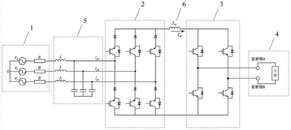
[0060] Such as image 3 As shown, the high-power electromagnetic exploration constant current transmitter provided in this embodiment includes a generator 1 , a rectifier 2 , an inverter bridge 3 and a transmitter electrode 4 connected in sequence. in:

[0061] Generator 1 is preferably a three-phase generator set, and each phase circuit is represented by a constant voltage source and a resistor connected in series;

[0062] Wherein preferably, after the generator 1, a filter 5 is also connected, preferably a three-phase LC filter, and its three-phase input end is correspondingly connected with the three-phase output end of the generator 1;

[0063] The rectifier 2 is preferably a three-phase bridge pulse width modulation PWM (Pulse Width Modulation) rectifier, and the three bridges are respectively connected to the three-phase output of the filter 5; two groups of switching devices are connected in series on each bridge; each group of switching devices consists of A diode a...

Embodiment 2

[0081] This embodiment provides a modulation method for a high-power electromagnetic exploration constant current transmitter, including:

[0082] Utilize the generator to provide electric energy for the constant current emission device;

[0083] Use a rectifier to convert electrical energy from AC to DC;

[0084] Use the inverter bridge to invert the DC into a rectangular pulse;

[0085] A rectangular pulse is emitted using the emitter electrode.

[0086] Wherein preferably, after the generator generates electric energy, a filter circuit is also used to perform harmonic filtering on the current generated by the generator.

[0087] Preferably, after the rectifier outputs the direct current, a filter inductor is used to stabilize the output direct current.

[0088] Preferably, when the rectifier is a pulse width modulation PWM rectifier, the DC current output by the rectifier and the power factor output by the generator are also detected and corrected.

[0089] Such as Fi...


PUM


Abstract

The invention provides a high-power electromagnetic exploration constant current transmitting device and a modulation method thereof. The device comprises: sequentially connecting a rectifier, an inverter bridge and a transmitting electrode. The rectifier, connected with the generator, is used to change the electric energy output by the generator from AC to DC; the inverter bridge is used to invert the DC output from the rectifier into a rectangular pulse; the transmitting electrode is used to emit a rectangular pulse; the A filter inductor is also connected in series between the rectifier and the inverter bridge to stabilize the current output by the rectifier. Wherein the rectifier is a pulse width modulation PWM rectifier. Compared with the existing electromagnetic transmitter, the present invention has simple topological structure, easy realization and strong practicability. And a pulse width modulation PWM rectifier is used to ensure that the device emits a constant current, and the power factor of the generator is unity power factor.

Description

technical field [0001] The invention relates to the technical field of resource exploration, in particular to a high-power electromagnetic exploration constant current transmitter and a modulation method thereof. Background technique [0002] With the continuous advancement of modern civilization, science and technology are changing with each passing day, and the consumption of resources is increasing day by day. Therefore, resource security has become one of the core contents of national security, and the level of resource exploration technology will directly affect the development and stability of my country's economic society. [0003] Electromagnetic prospecting is an emerging prospecting technology. The electrical prospecting launcher is a device for detailed inspection of ore bodies by using ground electrical methods. The ground electrical method is to inject a large current with changing frequency into the earth by the transmitter, and then receive the response of t...

Claims


Application Information

Patent Timeline
Patent Type & Authority Patents(China)
IPC IPC(8): H02M5/458G01V3/08
Inventor 张一鸣张加林原大康高俊侠
Owner BEIJING UNIV OF TECH
Why Eureka
Try Eureka