A Digital System and Implementation Method of Image Suppression in Low-IF Receiver

A low-IF receiver and image suppression technology, applied in transmission systems, electrical components, etc., can solve problems such as the impact of communication quality

Active Publication Date: 2018-01-16
GUANGZHOU RUNXIN INFORMATION TECH +1
View PDF3 Cites 0 Cited by
  • Summary
  • Abstract
  • Description
  • Claims
  • Application Information

AI Technical Summary

Problems solved by technology

If the mismatch is serious, the communication quality will be seriously affected

Method used


Image

  • A Digital System and Implementation Method of Image Suppression in Low-IF Receiver
  • A Digital System and Implementation Method of Image Suppression in Low-IF Receiver
  • A Digital System and Implementation Method of Image Suppression in Low-IF Receiver

Examples


Embodiment Construction

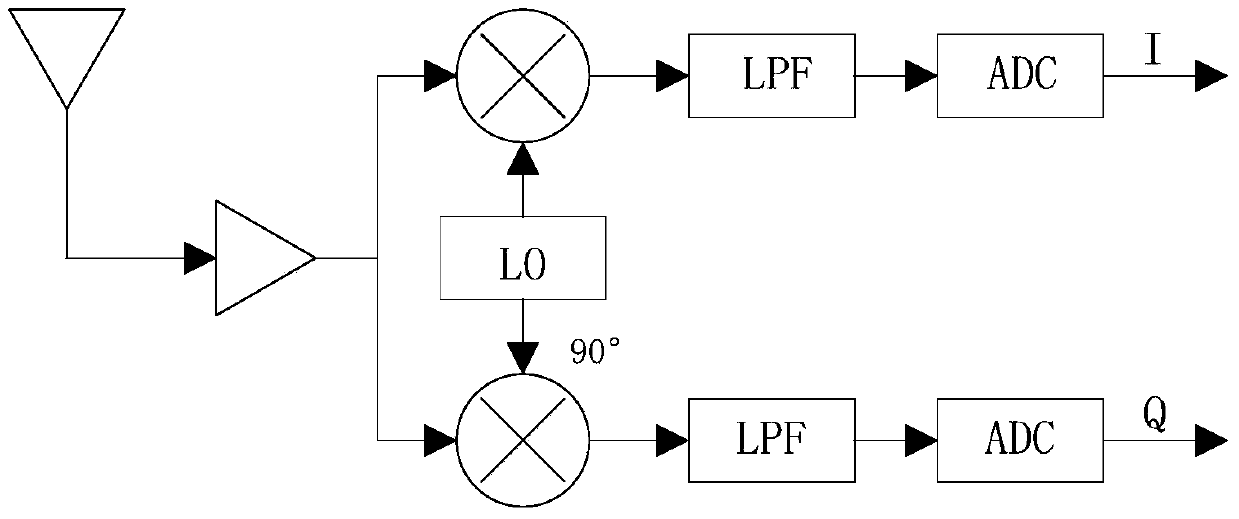
[0052] Below, in conjunction with accompanying drawing and specific embodiment, the present invention is described further:

[0053] The IQ mismatch introduced by the mixer can generally be represented by the following model:

[0054] x LO (t)=cos(ω LO t)-g*sin(ω LO t+θ)=K 1 *exp(-jω LO t)+K 2 *exp(jω LO t)

[0055] in,

[0056] Assuming that the ideal baseband signal is d(t), then after the RF signal r(t) passes through the mismatched mixer, the resulting mismatched signal can be expressed as:

[0057] x(t)=K 1 *d(t)+K 2 *d * (t)

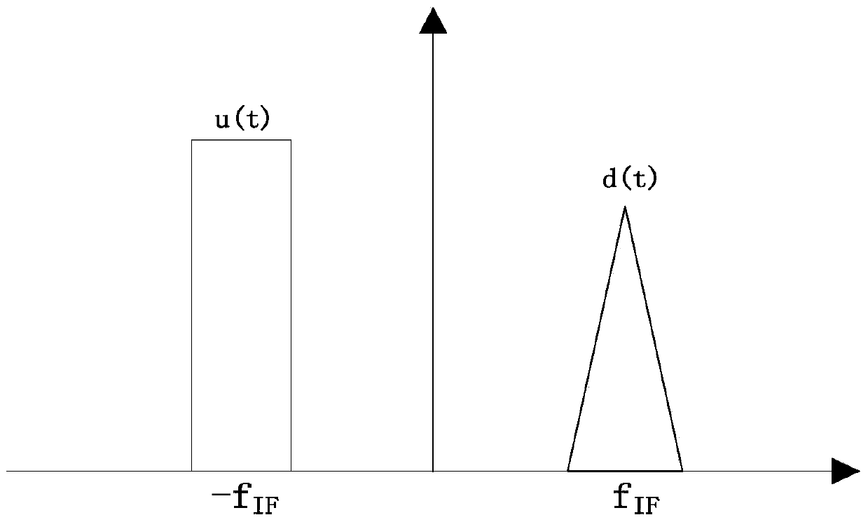
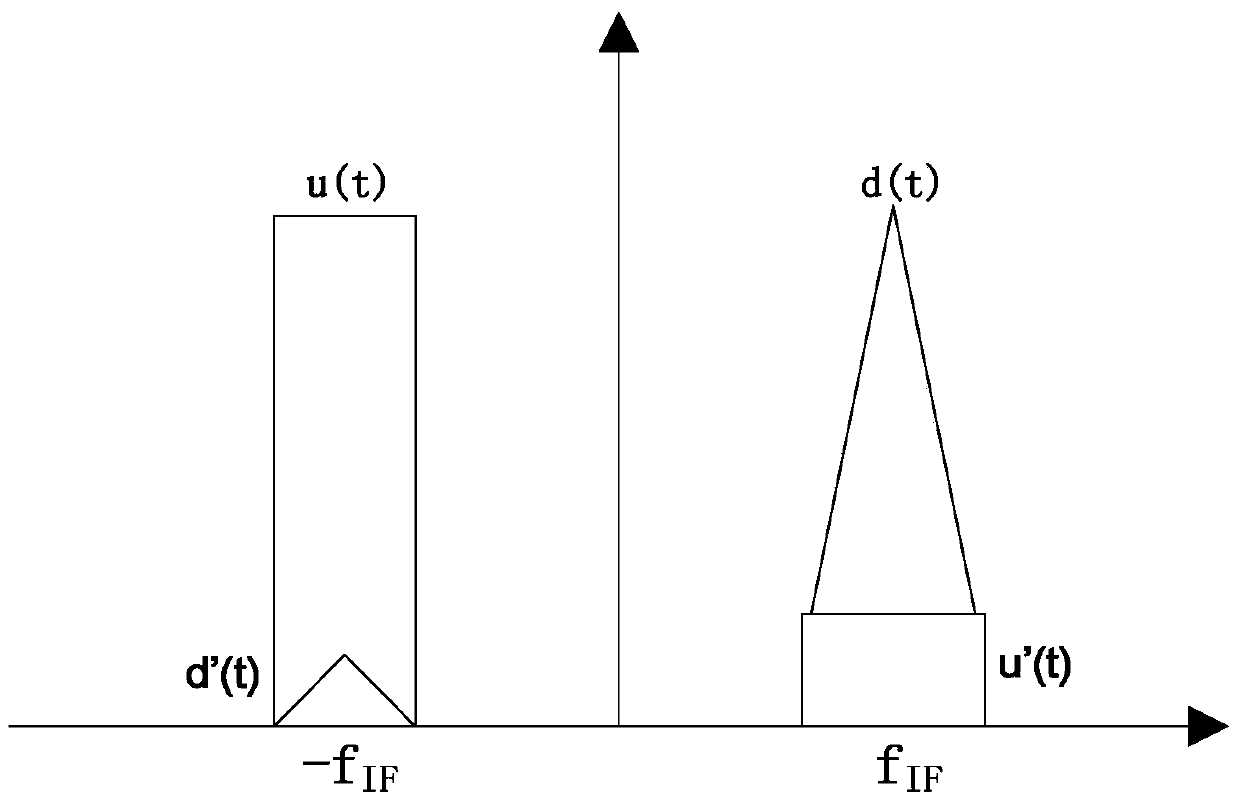
[0058] where d * (t) is the conjugate signal of d(t). Converted to the frequency domain, due to mixer mismatch, the signal d * (t) produces an image frequency symmetrical to the baseband signal. The image frequency is the result of IQ mismatch, if the image frequency is suppressed, then the IQ mismatch will be compensated.

[0059] For low-IF receivers, the -f IF and f IF There are two different signals u(t) and d(t), assuming ...


PUM


Abstract

The invention discloses a digital system for image rejection of a low-intermediate-frequency receiver and an implementation method thereof. The digital system comprises a direct-current calculation module, a first subtractor, a conjugated calculation module, a power calculation module, a self-adaptive filter calculation module and a plurality of band-pass filter modules; the direct-current calculation module is used for receiving I and Q data and outputting I0 and Q0 data; the first subtractor is used for receiving the I and Q data and the I0 and Q0 data so as to obtain I1 and Q1 data; the conjugated calculation module is used for receiving the I1 and Q1 data so as to obtain I2 and Q2 data; the power calculation module is used for receiving the I1 and Q1 data so as to obtain IQ-POW data; the self-adaptive filter calculation module is used for receiving the I1, Q1, I2, Q2 and IQ-POW data so as to obtain I4 and Q4 data; and the plurality of band-pass filter modules are used for receiving the I4 and Q4 data so as to obtain I5 and Q5 data. IQ mismatch can be improved obviously and stably although the digital system disclosed by the invention has a relatively simple structure.

Description

technical field [0001] The invention relates to the technical field of wireless communication, in particular to a digital image suppression system suitable for but not limited to low-IF receivers. Background technique [0002] The radio frequency part of a modern digital wireless communication receiver system generally includes the following analog circuits: band-pass filter, mixer, low-pass filter, gain control (AGC), and analog-to-digital converter (ADC). When the system uses the modulation method of in-phase (I) and quadrature (Q) signals, then we need to generate I and Q signals respectively at the radio frequency end from the modulation signals near the high-frequency carrier through frequency mixing and filtering ( Such as figure 1 shown). Ideal IQ signal, the signal amplitude is consistent, the phase difference is 90 degrees (such as figure 2 shown). However, when the analog circuit is implemented on the chip, due to the different physical positions of the corres...

Claims


Application Information

Patent Timeline
Patent Type & Authority Patents(China)
IPC IPC(8): H04B1/16
Inventor 陈焰强王日炎林汉雄万为陈红林
Owner GUANGZHOU RUNXIN INFORMATION TECH
Why Eureka
Try Eureka