Pipe connecting device

A technology of pipe connection and union nut, which is applied in the direction of hose connection device, pipe connection arrangement, non-removable pipe connection, etc. The effect of reducing deformation or creep, maintaining sealing performance, and increasing the number of repeated use

Active Publication Date: 2015-12-23
NIPPON PILLAR PACKING CO LTD
View PDF12 Cites 7 Cited by
  • Summary
  • Abstract
  • Description
  • Claims
  • Application Information

AI Technical Summary

Problems solved by technology

Therefore, in the conventional pipe connection device, for example, there are many situations where there are restrictions on the fastening position and the number of times of use, or the situation where repeated use such as timely replacement of parts is required in places where disassembly is frequently performed, there is still room for improvement. room

Method used


Image

  • Pipe connecting device
  • Pipe connecting device
  • Pipe connecting device

Examples


Embodiment approach 1

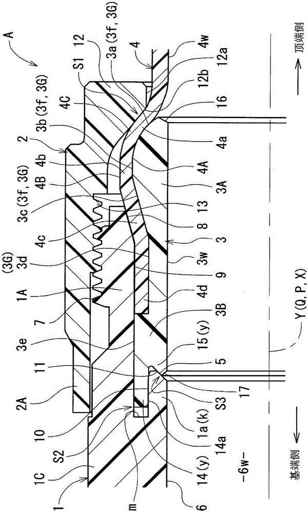
[0050] Such as figure 1 As shown, the pipe connecting device A is composed of pipe joints connecting pipes with each other, and has a pipe joint main body 1, a union nut 2, and an inner ring 3. The device starts to press into the end 4C of the tube 4 to connect the tube 4 in communication. The pipe joint main body 1, union nut 2, inner ring 3, and tube 4 are all made of resin such as fluororesin (eg, PTFE, PFA, ETFE, CTFE, ECTFE, etc.) excellent in heat resistance and chemical resistance. In addition, when the pipe joint main body 1, the inner ring 3, and the tube 4 are made of the above-mentioned fluororesin, the union nut 2 may be made of resin such as polyamide, polypropylene, or polyethylene. In addition, all of the pipe joint main body 1, the union nut 2, the inner ring 3, and the tube 4 can also be formed of resin such as polyamide, polypropylene, or polyethylene.

[0051] Such as figure 1 , Figure 4 As shown, the pipe joint main body 1 is a cylindrical structure, a...

Embodiment approach 2

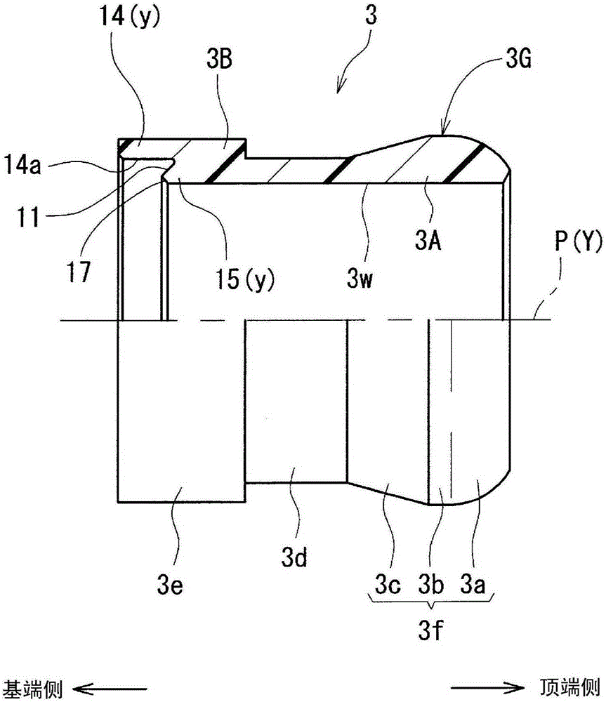
[0100] Such as Figure 5 As shown, the pipe connection device A of the second embodiment differs from the pipe connection device A of the first embodiment only in the structure of the fitting cylindrical portion 3B.

[0101] That is, the fitting tube portion 3B of the inner ring 3 is formed with an outer peripheral surface 3e, an inner peripheral portion 3w, and a base-end enlarged inner peripheral surface 20 whose diameter becomes larger toward the proximal end side. On the other hand, in the pipe joint main body 1, an outer peripheral surface 18 having an inclined outer peripheral surface 18 is formed on the radially inner side of the base end side of the cylindrical screwing portion 1A so that the diameter becomes smaller as it approaches the distal end side. The small-diameter cylindrical portion 1a. Between the outer peripheral surface 18 of the narrowed small-diameter cylindrical portion 1a and the inner peripheral surface 9 of the cylindrical threaded portion 1A, there...


PUM


Abstract

A pipe connecting device of the type using an inner ring is provided which, through further review of the structure, has been improved so as to allow more repeated use than conventionally possible even while maintaining good seal performance. This pipe connecting device is provided with: an inner ring (3) which has an inner ring (3) comprising an inner peripheral part (3w) and an outer peripheral part (3G) which has a tapered outer peripheral expanded surface (3a) which is press-fitted into and expands the end (4C) of a tube (4); a pipe fitting main body (1) which has a cylindrical screw part (1A) with a male screw (7) attached; and a union nut (2) having a female screw (13) that screws onto the male screw (7). The inner ring (3) provided with the tube (4) is inserted into the cylindrical screw part (1A), and the tapered outer peripheral expanded surface (3a) is pressed by a pressing portion (12b) of the union nut (2) with the tube (4) interposed therebetween, wherein the pressing portion (12b) of the union nut (2) that presses the tube (4) between the tapered outer peripheral expanded surface (3a) is formed as an inclined inner peripheral surface which, relative to the axis (Y) of the cylindrical screw part (1A), is inclined in the same direction as the tapered outer peripheral expanded surface (3a).

Description

technical field [0001] The present invention relates to a pipe connection device of the type using an inner ring, and specifically relates to a high-purity liquid suitable for use in manufacturing processes in various technical fields such as semiconductor manufacturing, medical and medical product manufacturing, food processing, and chemical industry , Pipe connection device for piping of ultrapure water. Background technique [0002] The pipe connection device using an inner ring has: a cylindrical threaded part protruding from the pipe joint body or fluid equipment in a state where an external thread is formed on the outer periphery; A diameter portion; a union nut formed with an internal thread screwed with an external thread; for example, a device disclosed in Patent Document 1 is known. [0003] In the device shown in this patent document 1, there are: a cylindrical threaded part provided on the pipe joint main body in a state in which an external thread is formed on ...

Claims


Application Information

Patent Timeline
Patent Type & Authority Applications(China)
IPC IPC(8): F16L33/22F16L19/04F16L47/04
CPCF16L19/028F16L33/223F16L47/041F16L13/147F16L15/08
Inventor 藤井睦饭田俊英
Owner NIPPON PILLAR PACKING CO LTD
Why Eureka
Try Eureka