Motor drive device

A driving device and motor technology, applied in the direction of motor control, electric controller, electrical components, etc., can solve the problem of not providing

Active Publication Date: 2015-12-23
PANASONIC INTELLECTUAL PROPERTY MANAGEMENT CO LTD
View PDF12 Cites 9 Cited by
  • Summary
  • Abstract
  • Description
  • Claims
  • Application Information

AI Technical Summary

Problems solved by technology

For this problem, the prior art does not provide any solution

Method used


Image

  • Motor drive device
  • Motor drive device
  • Motor drive device

Examples


Embodiment approach 1

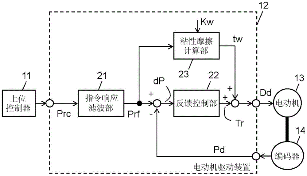
[0023] Figure 1A It is a block diagram including the motor drive device 12 according to Embodiment 1 of the present invention.

[0024] Such as Figure 1A As shown, the position command Prc generated by the host controller 11 to indicate the position is input to the motor drive device 12 . The motor drive device 12 generates a drive signal Dd based on the position command Prc, and drives the motor 13 with the drive signal Dd. Thereby, the position of the movable part of the motor 13 is controlled. The encoder 14 detects the position of the movable portion thus controlled, and notifies the motor drive device 12 as motor position information Pd.

[0025] In addition, in the motor drive device 12 , the command response filter unit 21 smoothes the input position command Prc, and outputs the filtered position command, that is, the filtered position command Prf. This smoothing is achieved using a primary delay filter, a secondary filter, a moving average filter, or the like that ...

Embodiment approach 2

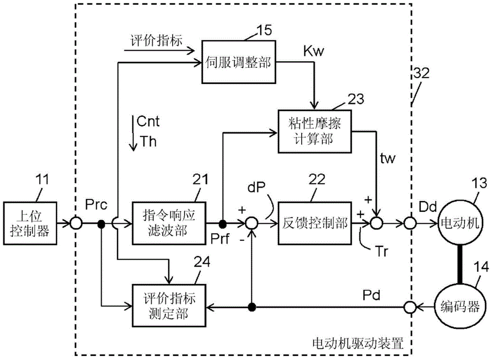
[0031] figure 2 It is a block diagram including the motor drive device 32 according to Embodiment 2 of the present invention.

[0032] exist figure 2 in, right with Figure 1A The same constituent elements are assigned the same reference numerals, and detailed description thereof will be omitted. figure 2 The motor driving device 32 of the second embodiment shown is equipped with Figure 1A In addition to the structure of , it also includes an evaluation index measurement unit 24 and a servo adjustment unit 15 .

[0033] The evaluation index measuring unit 24 receives the position command Prc and the motor position information Pd as input, and outputs an evaluation index.

[0034] In addition, the servo adjustment unit 15 changes the viscous friction coefficient Kw of the viscous friction calculation unit 23 , acquires the evaluation index obtained from the evaluation index measurement unit 24 every positioning operation, and determines the optimum value of the viscous fr...

Embodiment approach 3

[0057] Figure 8 It is a flowchart of viscous friction compensation processing executed by the servo adjustment unit 15 of the third embodiment.

[0058] Regarding steps 1, 2, 4, 4-1, and Figure 4 The same, but in the present embodiment, in step 3, the evaluation index measuring unit 24 measures the positioning settling time. In addition, after the trial times are executed, the viscous friction coefficient Kw that minimizes the positioning settling time is output in step 5 .

[0059] Thus, in the present embodiment, the servo adjustment unit 15 determines the optimum value of the viscous friction coefficient Kw so as to minimize the positioning settling time. Then, the servo adjustment unit 15 sets the optimum viscous friction coefficient Kw thus determined to the viscous friction calculation unit 23 .

[0060] In this method, with Figure 7 It can be seen from the change of the positioning settling time of , that the same viscous friction coefficient Kw=8 as in the secon...


PUM


Abstract

A motor drive device according to the present invention drives a motor while carrying out feedback control so that an actual operation follows a command. The motor drive device comprises: a feedback control unit for carrying out feedback control by outputting a torque command; and a viscous friction calculation unit for calculating a viscous friction torque compensation value by multiplying a speed command by a viscous friction coefficient. The motor drive device drives a motor on the basis of a drive signal created by adding the viscous friction torque compensation value to the torque command. The motor drive device is provided with an evaluation index measurement unit for measuring an overshoot amount and positioning stabilization time by inputting a position command and a motor position or a load position, and a servo adjustment unit for carrying out positioning operations a plurality of times by changing a viscous friction coefficient and determining a viscous friction coefficient so that the overshoot amount is a designated value or the positioning stabilization time is the minimum value.

Description

technical field [0001] The invention relates to a motor drive device for controlling and driving a servo motor, in particular to a motor drive device with a viscous friction compensation function. Background technique [0002] In the control of the servo motor, for shortening the positioning settling time and improving the trajectory tracking accuracy, it is important to properly compensate the friction torque generated by the action of the motor and the load. The portion of the friction torque that has a fixed value such as an eccentric load or a motion friction torque can be compensated by an integral term of a feedback control system. However, since the viscous friction changes in proportion to the motor speed, it is too late to perform integral compensation, causing overshooting during positioning setting and poor tracking accuracy during trajectory control. [0003] As a compensation method for this viscous friction torque, Patent Document 1 proposes, for example. Thi...

Claims


Application Information

Patent Timeline
Patent Type & Authority Applications(China)
IPC IPC(8): H02P29/00G05B11/36
CPCH02P23/0004H02P2205/05
Inventor 铃木健一西园胜藤原弘
Owner PANASONIC INTELLECTUAL PROPERTY MANAGEMENT CO LTD
Why Eureka
Try Eureka