Motor hold shaft installation type permanent-magnetic direct-drive bogie

A technology of permanent magnet direct drive and shaft installation, which is applied in the field of rail vehicle bogies, and can solve problems such as the difficulty in significantly improving bogie performance indicators such as energy saving, low transmission efficiency of gearbox couplings, and large wheelbases of bogie wheels. problem, to achieve the effect of ensuring the passing performance of small curves, improving the passing performance of small curves, and small size

Inactive Publication Date: 2015-12-30
CRRC NANJING PUZHEN CO LTD
View PDF6 Cites 25 Cited by
  • Summary
  • Abstract
  • Description
  • Claims
  • Application Information

AI Technical Summary

Problems solved by technology

[0002] In the structural design of traditional bogies, AC asynchronous motors are generally used to drive. Due to the need for rotor electric excitation, the efficiency of the motor is not high enough, and the energy consumption is large. The motor is elastically or rigidly mounted on the frame. Disturbance and torque transmission require the installation of complex couplings and gearboxes. This kind of bogie has a complex structure, the transmission efficiency of the gearbox coupling is low, and the wheelbase of the bogie is large and heavy. Make it difficult to significantly improve performance indicators such as small curve passing performance and energy saving of the bogie

Method used


Image

  • Motor hold shaft installation type permanent-magnetic direct-drive bogie
  • Motor hold shaft installation type permanent-magnetic direct-drive bogie
  • Motor hold shaft installation type permanent-magnetic direct-drive bogie

Examples


Embodiment Construction

[0037] The present invention will be further explained below in conjunction with the accompanying drawings and specific embodiments. It should be understood that the following specific embodiments are only used to illustrate the present invention but not to limit the scope of the present invention.

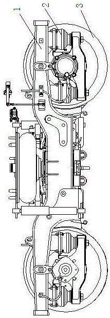
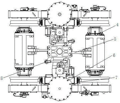
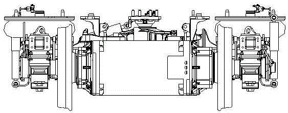
[0038]It can be seen from the accompanying drawings that the motor shaft-mounted permanent magnet direct drive bogie is used to be installed under the rail vehicle and used for steering during the running of the rail vehicle. Each bogie includes a frame device 1, two A permanent magnet synchronous traction motor 4, two triangular elastic support devices 5, and two wheel-to-axle box devices 3, the two wheel-to-axle box devices 3 are arranged in a rectangular array below the rail vehicle, located at the front of the rail vehicle in the forward direction The two adjacent wheel-to-axlebox devices 3 are connected by the frame device 1, and the two wheel-to-axlebox devices 3 located on ...


PUM


Abstract

A motor hold shaft installation type permanent-magnetic direct-drive bogie comprises two frame devices, two permanent-magnetic synchronous traction motors, two triangular elastic supporting devices and four wheel pair box devices, wherein two adjacent front and rear wheel pair box devices are connected through the frame devices, two wheels on the left and right symmetric sides are connected through an axel, the permanent-magnetic synchronous traction motors and the axle are integrated through rotors, and driving is realized by rotating the axel; the two frame devices are symmetrically located on the left side and the right side of the advancing direction of a railway vehicle and are connected by double traction rod devices, and the triangular elastic supporting devices are connected with the permanent-magnetic synchronous traction motors and the double traction rod devices. According to the motor hold shaft installation type permanent-magnetic direct-drive bogie, the permanent-magnetic synchronous traction motors are adopted, rotor excitation power is saved, the motor efficiency is improved, the transmission efficiency is improved further after a gear box device is saved, the wheel base of the bogie is shortened, and the motor hold shaft installation type permanent-magnetic direct-drive bogie has the advantages that energy is saved, environment is protected and the small curve through capacity is high, and can be widely applied to various urban railway traffic vehicles.

Description

technical field [0001] The invention relates to a permanent magnet direct-drive bogie mounted on a motor shaft, and belongs to the technical field of rail vehicle bogies. Background technique [0002] In the structural design of traditional bogies, AC asynchronous motors are generally used to drive. Due to the need for rotor electric excitation, the efficiency of the motor is not high enough, and the energy consumption is large. The motor is elastically or rigidly mounted on the frame. Disturbance and torque transmission require the installation of complex couplings and gearboxes. This kind of bogie has a complex structure, the transmission efficiency of the gearbox coupling is low, and the wheelbase of the bogie is large and heavy. It is difficult to significantly improve performance indicators such as small curve passing performance and energy saving of the bogie. Contents of the invention [0003] In order to solve the above-mentioned existing problems, the present inv...

Claims


Application Information

Patent Timeline
Patent Type & Authority Applications(China)
IPC IPC(8): B61C9/50B61F5/30
CPCB61C9/46
Inventor 胡定祥楚永萍赵旭东冯遵委陈德强金鑫孙海东贾小平肖遥张羽张杨祝航
Owner CRRC NANJING PUZHEN CO LTD
Why Eureka
Try Eureka