Multifunctional pulsator washing machine
A pulsator washing machine and multi-functional technology, which can be applied to other washing machines, washing machines with containers, control devices of washing machines, etc., can solve the problems of incomplete commutation, damaged commutation devices, etc., and achieve simple structure, large laundry volume, Ensure the effect of laundry effect and dehydration effect
- Summary
- Abstract
- Description
- Claims
- Application Information
AI Technical Summary
Problems solved by technology
Method used
Image
Examples
Embodiment 1
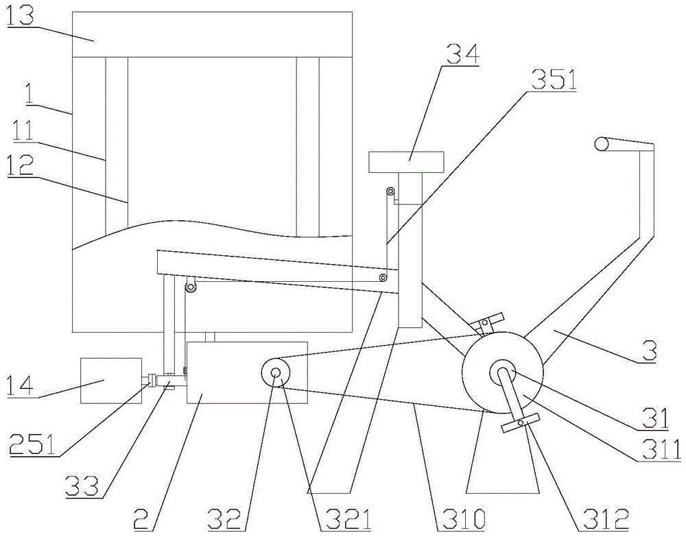
[0029] refer to Figure 1 to Figure 6 , a multifunctional pulsator washing machine, comprising a cabinet 1, the top of the cabinet 1 is provided with a control seat 13, and the inside of the cabinet 1 is coaxially provided with a water bucket 11 and a dehydration bucket 12 from the outside to the inside, and the cabinet 1 The outside of the washing machine is provided with a washing motor 14, a reduction box 2 and a fixed frame 3;
[0030] Described fixed mount 3 is provided with front axle 31 and rear axle 32, and described front axle 31 is provided with front sprocket 311, and described rear axle 32 is provided with rear sprocket 321, and described front chain The wheel 311 and the rear sprocket 321 are connected through a chain 310, and the front axle 31 is provided with a pedal 312;
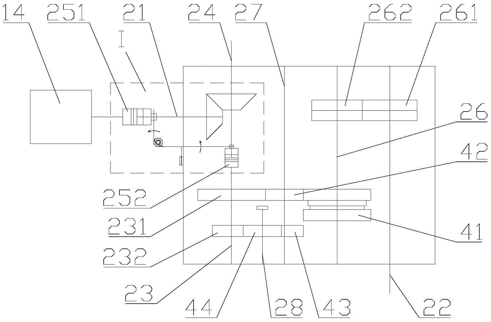
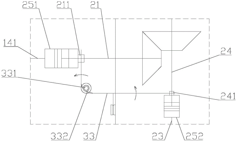
[0031] The reduction box 2 includes a first input shaft 21, a second input shaft 22, an intermediate shaft 23 and an output shaft 24; the first input shaft 21 is connected to the motor shaft...
Embodiment 2
[0040] Such as Figure 7 As shown, this embodiment is similar to Embodiment 1, the difference is:
[0041] The fixed frame 3 is provided with a handle 37, and the control mechanism is a clutch wrench 36 connected in rotation on the handle. A second wire rope 352 is connected between the clutch wrench 36 and the lever 33. One end of the two wire ropes 352 is connected to the clutch wrench 36, and the other end is connected between the pin shaft 331 and the end connected to the second sleeve on the lever; after the lever 33 drives the second sleeve away from the second clutch, the clutch wrench 36 is relatively The handle is opened; when the clutch wrench 36 and the handle 37 are closed, the lever 33 drives the second sleeve close to the second clutch; the clutch wrench 36 and the handle 37 are provided with a spring that makes the clutch wrench and the handle open, so The above-mentioned handle is provided with a lock catch that locks the closed clutch wrench and the handle. ...
Embodiment 3
[0044]In this embodiment, the clutch control is simpler and more convenient. Both the first clutch 251 and the second clutch 252 are electromagnetic clutches. The control seat 13 is provided with a power selection switch and a control circuit. The first clutch 251, the second clutch 252, the The selector switch is connected in the control circuit, the power selector switch is a single-pole double-throw switch, the power selector switch has a first position and a second position, the first position is on, the second position is off, the first clutch 251 is engaged, the second The second clutch 252 is in a disengaged state, the first position is disconnected, the second position is turned on, the first clutch 251 is in a disengaged state, and the second clutch 252 is in an engaged state. After starting the washing machine, the user can select whether it is an electric washing machine or a human-driven washing machine by operating the power selection switch, which is intuitive and...
PUM
 Abstract
Description
Claims
Application Information
 - R&D
- Intellectual Property
- Life Sciences
- Materials
- Tech Scout
- Unparalleled Data Quality
- Higher Quality Content
- 60% Fewer Hallucinations
Browse by: Latest US Patents, China's latest patents, Technical Efficacy Thesaurus, Application Domain, Technology Topic, Popular Technical Reports.
© 2025 PatSnap. All rights reserved.Legal|Privacy policy|Modern Slavery Act Transparency Statement|Sitemap|About US| Contact US: help@patsnap.com


