Optical fiber grating temperature detecting method and device

A fiber grating and detection method technology, applied in the field of sensors, can solve the problem of small spectrum range of demodulated optical signals, and achieve the effect of expanding the spectrum range and improving the recognition range

Active Publication Date: 2015-12-30
STATE GRID CORP OF CHINA +1
View PDF8 Cites 3 Cited by
  • Summary
  • Abstract
  • Description
  • Claims
  • Application Information

AI Technical Summary

Problems solved by technology

[0005] The invention provides a fiber grating temperature detection method and device, which are used to solve the shortcomings of the existing fiber grating demodulation system, such as the small spectrum range of the demodulated optical signal.

Method used


Image

  • Optical fiber grating temperature detecting method and device
  • Optical fiber grating temperature detecting method and device
  • Optical fiber grating temperature detecting method and device

Examples


Embodiment 1

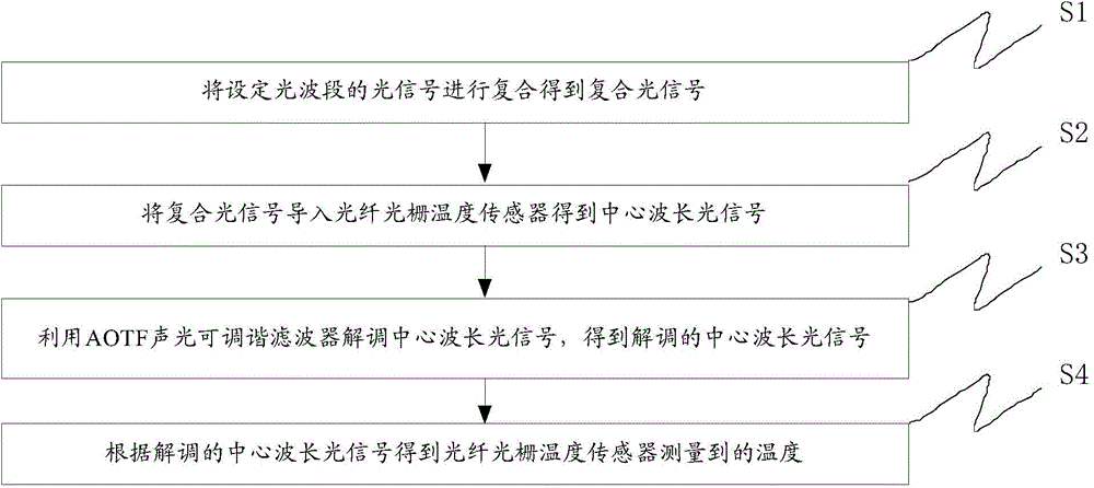
[0044] This embodiment provides a fiber grating temperature detection method, the flow chart of this embodiment is as follows figure 1 As shown, the method includes the following steps:

[0045] S1: Composite the optical signal of the set optical band to obtain the composite optical signal;

[0046] S2: Lead the composite optical signal into the fiber grating temperature sensor to obtain the central wavelength optical signal;

[0047] S3: using the AOTF acousto-optic tunable filter to demodulate the central wavelength optical signal to obtain the demodulated central wavelength optical signal;

[0048] S4: Obtain the temperature measured by the fiber grating temperature sensor according to the demodulated central wavelength optical signal.

[0049] The method of this embodiment adopts the optical signal of the set band (C band, L band or other bands) to expand the spectrum range of the optical signal; and extracts the corresponding set band (C band) from the optical signal re...

Embodiment 2

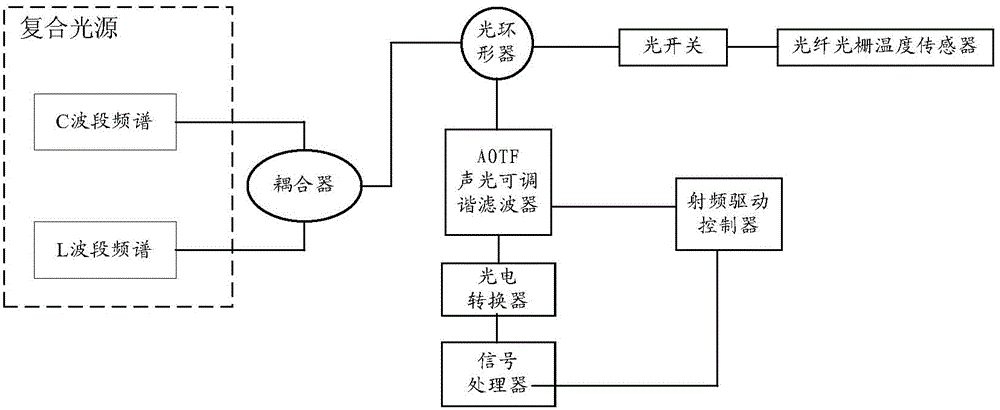
[0068] This embodiment and Embodiment 1 belong to the same inventive concept. This embodiment provides a fiber grating temperature detection device. The structure diagram of this embodiment is as follows figure 2 As shown, the device includes:

[0069] The composite light source is used to provide multiple optical signals of a set optical band; the composite light source can include multiple sub-light sources, and the sub-light source can be an ASE (Amplified Spontaneous Emission, amplified spontaneous emission source) broadband light source. The frequency spectrum of the optical signal of the sub-light source may include C-band and L-band;

[0070] a coupler for recombining optical signals;

[0071] An optical circulator is used to realize bidirectional transmission of optical signals;

[0072] An optical switch is used for channel switching of the composite optical signal (the optical switch includes one or more transmission windows, and the transmission window is used fo...

Embodiment 3

[0087] The present application is described below through a specific scenario.

[0088] In this embodiment, AOTF acousto-optic tunable filter technology will be adopted, and a fiber grating temperature detection device based on AOTF demodulation technology will be designed by utilizing the characteristics of high speed and wide dynamic range of AOTF acousto-optic tunable filter. The appearance of the device will greatly meet the large-scale and high-speed demodulation requirements of the temperature sensing monitoring system.

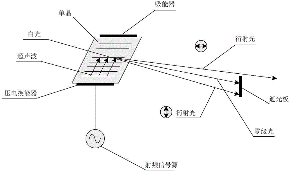
[0089] Fiber Bragg grating temperature sensing technology principle:

[0090] Fiber Bragg grating uses the photosensitivity of the fiber material to write the coherent field pattern of the incident light into the fiber core by ultraviolet light exposure, and produces a periodic change in the refractive index along the axis of the fiber core in the fiber core, thereby forming a spatial phase grating. . When the temperature of the fiber grating changes,...


PUM


Abstract

The invention discloses an optical fiber grating temperature detecting method and a device in the technical field of sensors. The method comprises the steps as follows: first, compositing optical signals in a set optical band to obtain a composite optical signal; then, importing the composite optical signal into an optical fiber grating temperature sensor to get a center wavelength optical signal; next, using an AOTF acousto-optic tunable filter to demodulate the center wavelength optical signal to obtain a demodulated center wavelength optical signal; and finally, working out the temperature measured by the optical fiber grating temperature sensor according to the demodulated center wavelength optical signal. According to the invention, optical signals of a set optical band are provided by a composite light source, and the spectral range of optical signals is expanded; and the AOTF acousto-optic tunable filter is adjusted by a radio frequency drive controller, a demodulated center wavelength signal corresponding to the set band can be extracted from optical signals returned by the optical fiber grating temperature sensor, the spectrum identification range of optical signals is expanded, and the requirements of a large-scale temperature sensing monitoring system can be met.

Description

technical field [0001] The present invention relates to the technical field of sensors, in particular to a fiber grating temperature detection method and device. Background technique [0002] The tunable fiber Fabry-Perot filter (FFP) has been widely used in signal demodulation of sensing gratings. The filter can be described by the band-pass response of the Lorentz spectral line shape. The typical 3dB spectral linewidth is 0.3 nanometers. in the range of tens of nanometers. [0003] The tunable optical fiber Fabry-Perot cavity is driven by piezoelectric ceramics, and a periodic sawtooth wave voltage signal is applied to change the cavity length, so as to realize periodic filter scanning of the wavelength in a certain region. It can sequentially query the wavelength information of each fiber Bragg grating sensor element within the measurement range, and compare the measured wavelength information with the wavelength information before the offset to obtain the wavelength off...

Claims


Application Information

Patent Timeline
IPC IPC(8): G01K11/32G02F1/11G01K11/3206
Inventor 陈泽贵何凡梁小斌李小娟
Owner STATE GRID CORP OF CHINA
Why Eureka
Try Eureka