Machine vision based precision compensation method

A technology of precision compensation and machine vision, applied in instruments, image data processing, computing, etc., can solve the problems of high cost, high cost, large error, etc., and achieve the effect of reducing error and low cost

Active Publication Date: 2015-12-30
广东科杰技术股份有限公司
View PDF5 Cites 12 Cited by
  • Summary
  • Abstract
  • Description
  • Claims
  • Application Information

AI Technical Summary

Problems solved by technology

The error caused by the imaging module is the largest, and the cost of reducing this error is particularly expensive. For example, a better lens (such as a telecentric lens) can be used to reduce radial distortion, or a higher-precision camera can be used, and special instruments can be used. To detect the installation accuracy of the lens and camera to reduce

Method used


Image

  • Machine vision based precision compensation method
  • Machine vision based precision compensation method
  • Machine vision based precision compensation method

Examples


Embodiment Construction

[0021] The present invention will be described and analyzed in further detail below by means of the accompanying drawings and examples.

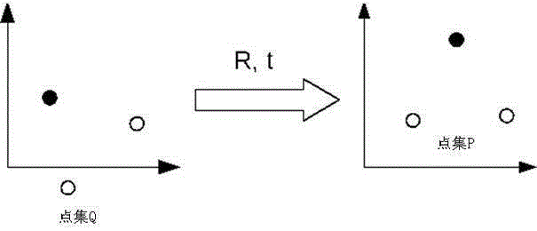
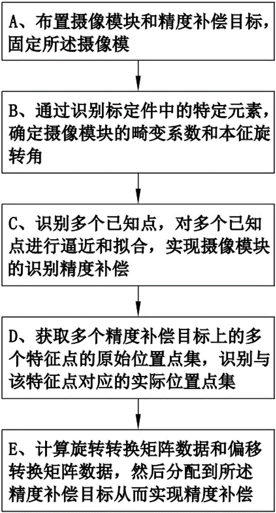
[0022] refer to figure 1 Shown is a flow chart of the steps of the accuracy compensation method based on machine vision according to the present invention. The method includes the following steps: A. arranging the camera module and the precision compensation target, fixing the camera module, and making the precision compensation target movably within the field of view of the camera module; B. Specific elements, determine the distortion coefficient and intrinsic rotation angle of the camera module; C, identify multiple known points at preset positions through the camera module, and then use the regularized network interpolation algorithm and preset penalty coefficients to Approximate and fit the identification values ​​of the above-mentioned multiple known points, so as to realize the identification accuracy compensation of the camera module...


PUM


Abstract

The invention discloses a machine vision based precision compensation method. The method comprises the following steps: arranging a camera module and a precision compensation target; through identifying a specific element in a calibration member, determining a distortion coefficient and an intrinsic rotation angle of the camera module; carrying out approximation and fitting on identification values of multiple known points by use of a regularization network interpolation algorithm and a preset punishment coefficient; identifying an actual position point set corresponding to multiple characteristic points through the camera module; and according to an original position point set and an actual position point set, calculating rotation conversion data and offset conversion data by use of an iteration algorithm, and then distributing the rotation conversion data and the offset conversion data to the precision compensation target. The method provided by the invention has the following advantages: errors caused by manual positioning by use of a conventional vision positioning device or an automatic device are substantially reduced, and a series of complete precision compensation schemes ranging from parameter compensation of the camera module itself to coordinate and path compensation of a target of the automatic device are realized.

Description

technical field [0001] The invention relates to an accuracy compensation method based on machine vision, which is suitable for coordinate and path compensation of automation equipment. Background technique [0002] With the rapid development of my country's manufacturing industry, the precision requirements for production equipment are also getting higher and higher. At present, the most effective solution to improve the precision is to adopt various precision compensation techniques. In the field of automation equipment, the role of the machine vision system is to calculate the rotation and deviation of the actual coordinates of the workpiece on the workbench relative to the original coordinates by identifying several feature points (also called Mark points) passing through the workpiece. displacement. After the numerical control system of the automation equipment obtains the rotation and offset, it can correct the origin of the original coordinates and the motion path (f...

Claims


Application Information

Patent Timeline
IPC IPC(8): G06T7/00
CPCG06T7/0004G06T2207/30164
Inventor 田少华
Owner 广东科杰技术股份有限公司
Why Eureka
Try Eureka